
MEC-430 · Lesson 8 of 12 · 21 min
Hydronic systems, terminal units and the district energy connection
In the system chosen in Lesson 6, water carries most of the heating and cooling: heating water from the energy transfer station to the fan coils, radiant panels and DOAS heating coil, and chilled water to the fan coils and the DOAS cooling coil. This lesson designs those hydronic systems, from the flows and pipe sizes to the pumps and the connection to Northgate's district networks, and explains why the temperatures chosen matter as much to the utility as to the building.
Flow, temperature difference and the design temperatures
The water flow needed to carry a load is set by the load and the temperature difference between supply and return. A large temperature difference means less flow, smaller pipes and less pumping energy, and, for a district customer, more capacity on the network for the same pipes. The design temperatures are therefore a deliberate choice, not a convention.
For heating the team chose 55 °C supply and 40 °C return, a 15 K difference, so that the building can later run from heat pumps and returns cool water to Northgate's hot-water network. For chilled water it chose 7 °C supply and 15 °C return, an 8 K difference, larger than the traditional 5.5 K, because district cooling plants make their chilled water more efficiently, and move it more cheaply, when the return is warm. A cooling coil designed for a 15 °C return needs more rows or more surface than one designed for 12 °C, and the coil selections are made at the design temperatures from the start.
Pipe sizing and pumps
Pipes are sized to keep the friction loss and velocity within limits that balance pump energy against pipe cost, avoid noise and erosion, and keep air from collecting. A common design range is 150 to 400 Pa per metre of friction, with velocities up to about 1.2 m/s in small pipes and 2 to 3 m/s in large mains. The pump must overcome the friction along the index circuit, the hydraulically most remote path, plus the pressure drops of the coils, control valves and the heat exchanger. Variable-speed pumps controlled from a differential pressure sensor near the end of the system are standard, and modern practice reduces the setpoint as valves close, in the same way as the duct static pressure reset in Lesson 10.
# Hydronic design: flows, pipe sizes, pump power and the district energy transfer station heat exchangers
import math
SITE = 'ca'
heat = {'ca': 222.0, 'us': 195.0}[SITE]              # kW design heating (lesson 4)
cool = 340.0                                          # kW block cooling (lesson 5)
cp = 4.19
loops = [('heating water 55/40 C', heat, 15.0, 988.0, 0.00055), ('chilled water 7/15 C', cool, 8.0, 999.0, 0.0013)]
def size(q, rho, mu, limit=300.0):                   # smallest schedule-40-like inside diameter with friction below limit Pa/m
    for D in (0.0409, 0.0525, 0.0627, 0.0779, 0.1023, 0.1282, 0.1541, 0.2027):
        v = q/(math.pi*D*D/4); Re = rho*v*D/mu; f = 0.02
        for _ in range(40): f = (-2*math.log10(4.6e-5/(3.7*D) + 2.51/(Re*math.sqrt(f))))**-2
        g = f*rho*v*v/(2*D)
        if g <= limit: return D, v, g
for name, load, dT, rho, mu in loops:
    m = load/(cp*dT); q = m/rho
    D, v, g = size(q, rho, mu)
    head = (g*1.5*180 + 2*45e3)/(rho*9.81)          # 180 m index circuit with 50 % for fittings, 2 x 45 kPa coil/valve/heat exchanger
    P = rho*9.81*q*head/0.55/1000
    print(f"{name:22s}: {m:5.2f} kg/s, main {D*1000:.0f} mm ID at {v:.2f} m/s, {g:.0f} Pa/m, pump head {head:.1f} m, {P:.2f} kW")
# Low delta-T: if the chilled water returns at 12 C instead of 15 C, the same load needs more flow
for dT in (8, 5):
    print(f"chilled water dT {dT} K: {cool/(cp*dT):.1f} kg/s, pump power ~ {(cool/(cp*dT)/(cool/(cp*8)))**3:.2f} x design")
# Energy transfer station: district hot water (supply 105 C at winter design) heating building water 40 -> 55 C
def hx(Cmin, Cmax, NTU):                             # counterflow plate exchanger effectiveness
    Cr = Cmin/Cmax
    return (1 - math.exp(-NTU*(1 - Cr)))/(1 - Cr*math.exp(-NTU*(1 - Cr))) if Cr < 1 else NTU/(1 + NTU)
Tdh, Tret_target = 105.0, 45.0                        # district supply and the utility's return target, C
Cb = heat/15.0; Cd = heat/(Tdh - Tret_target)         # kW/K
eps = heat/(min(Cb, Cd)*(Tdh - 40.0))
lmtd = ((Tdh - 55) - (Tret_target - 40))/math.log((Tdh - 55)/(Tret_target - 40))
UA = heat/lmtd
print(f"Heating ETS: district 105 -> 45 C, building 40 -> 55 C: effectiveness {eps:.2f}, LMTD {lmtd:.1f} K, UA {UA:.1f} kW/K, "
      f"area {UA*1000/4500:.1f} m2 at U = 4,500 W/m2K")
NTU = UA/min(Cb, Cd); print(f"  check: NTU {NTU:.2f} gives effectiveness {hx(min(Cb, Cd), max(Cb, Cd), NTU):.2f}")
# Cooling ETS: district chilled water 5.5 C supply, building 7/15 C, approach 1.5 K at the cold end
lm = ((15 - 13.5) - (7 - 5.5))
print(f"Cooling ETS: district 5.5 -> 13.5 C, building 15 -> 7 C, both ends 1.5 K: LMTD 1.5 K, UA {cool/1.5:.0f} kW/K, "
      f"area {cool/1.5*1000/5500:.0f} m2 at U = 5,500 W/m2K")
print(f"  district chilled water flow {cool/(cp*8):.1f} kg/s; every 1 K the building's return falls short costs the utility "
      f"{100*(1 - 7/8):.0f} % of its pipe capacity")
if SITE == 'us':
print(f"US units: heating {heat/(cp*15)*15.85:.0f} gpm, chilled water {cool/(cp*8)*15.85:.0f} gpm")heating water 55/40 C : 3.53 kg/s, main 63 mm ID at 1.16 m/s, 218 Pa/m, pump head 15.4 m, 0.97 kW chilled water 7/15 C : 10.14 kg/s, main 102 mm ID at 1.24 m/s, 151 Pa/m, pump head 13.3 m, 2.41 kW chilled water dT 8 K: 10.1 kg/s, pump power ~ 1.00 x design chilled water dT 5 K: 16.2 kg/s, pump power ~ 4.10 x design Heating ETS: district 105 -> 45 C, building 40 -> 55 C: effectiveness 0.92, LMTD 19.5 K, UA 11.4 kW/K, area 2.5 m2 at U = 4,500 W/m2K check: NTU 3.07 gives effectiveness 0.92 Cooling ETS: district 5.5 -> 13.5 C, building 15 -> 7 C, both ends 1.5 K: LMTD 1.5 K, UA 227 kW/K, area 41 m2 at U = 5,500 W/m2K district chilled water flow 10.1 kg/s; every 1 K the building's return falls short costs the utility 12 % of its pipe capacity
Results for the health centre
The program gives a heating water flow of about 3.5 kg/s in a 63 mm main and a chilled water flow of about 10.1 kg/s in a 102 mm main, with pump powers of about 1.0 kW and 2.4 kW at design. These are small numbers compared with the fan powers of Lesson 6, which is the hydronic system's great advantage. The program also shows the cost of a low temperature difference. If the chilled water returns at 12 °C instead of 15 °C, the same load needs 60 percent more flow, and the pumping power, which varies roughly with the cube of flow in a fixed system, rises about fourfold. In a district system the cost falls on the utility as well: the distribution pipes are sized for a design temperature difference, and every building that returns water too cold uses capacity that other customers paid for.
Low delta-T syndrome
The problem is common enough to have a name. Chilled water systems in many buildings operate with temperature differences far below design, so that the plant must pump much more water than intended and chillers cannot be loaded fully. The causes are mostly in the building: coils that are oversized or fouled, three-way valves that bypass cold supply water into the return, control valves that are oversized and hunt, coils piped backwards, supply temperatures set colder than needed, and fan coils whose fans stop while their valves remain open. The cures are equally well known: two-way valves throughout, pressure-independent control valves that hold a set flow regardless of system pressure, coils selected for the design temperature difference, and controls that close the valve when the fan is off. Northgate's service agreement sets a minimum return temperature and charges customers who fall below it, which concentrates the designer's mind.
The energy transfer station
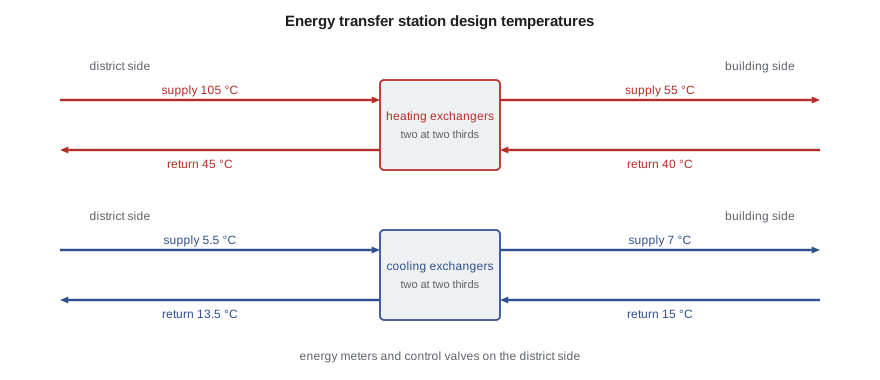
The energy transfer station keeps the district water and the building water separate. A plate heat exchanger for heating and another for cooling transfer energy between them; the district side has a control valve that modulates district flow to hold the building supply temperature, and an energy meter, a flow meter with paired temperature sensors, for billing. Separation protects the district network from the building's water quality and pressure problems and lets the building run at its own pressures, which matters in a tall building on a low-pressure network.
For heating, the district supply at design is 105 °C and Northgate's target return is 45 °C or lower. Heating building water from 40 to 55 °C, the exchanger has a log-mean temperature difference of about 19.5 K and needs a UA of about 11.4 kW/K, only about 2.5 square metres of plate area at the typical overall coefficient of 4,500 W/m²K that Northgate measured on its substation exchanger in MEC-340. The exchanger is small because the temperature difference is large. In mild weather Northgate resets its supply to 75 °C, and the exchanger still meets the building's reduced load. Graham insists on two exchangers, each sized for two thirds of the load, so that one can be cleaned or repaired while the other runs.
Cooling is harder. The district chilled water arrives at 5.5 °C and the building wants 7 °C supply, so the cold-end approach is only 1.5 K. Northgate wants its water back at 13.5 °C, so with building water returning at 15 °C the warm-end approach is also 1.5 K. The log-mean temperature difference is then just 1.5 K, and the exchanger needs a UA of about 227 kW/K, about 41 m² of plate area even at a high overall coefficient. Close-approach plate exchangers are routine for district cooling, but they are large and expensive, and every tenth of a kelvin of approach matters. A cooler supply in the building would make the exchanger smaller but would lower the return; a warmer one would help the exchanger but make the coils bigger. The 7/15 °C choice is the compromise.
| Exchanger | District side (°C) | Building side (°C) | LMTD (K) | Approximate area |
|---|---|---|---|---|
| Heating | 105 → 45 | 40 → 55 | about 19.5 | about 2 to 2.5 m² in total |
| Cooling | 5.5 → 13.5 | 15 → 7 | 1.5 | about 41 m² in total |
Terminal units and coils
The fan coils are selected for both duties at the building's water temperatures: cooling with 7 °C water rising to 15 °C, and heating with 55 °C water falling to 40 °C. Because the DOAS dries the ventilation air, the fan coils' cooling coils run dry most of the time, but they still have drain pans for the rare humid day when the DOAS is out of service. The perimeter radiant ceiling panels are piped in series with the fan coil heating coils in each perimeter room, so that the water is cooled twice before it returns. The DOAS heating coil uses 55 °C water downstream of the energy recovery wheel; its coldest entering air, during wheel frost control, is about −15 °C, and the coil has a freeze protection pump that keeps water moving through it.
Two water systems, heating and chilled water, run to every room with four-pipe fan coils, which is the main capital cost of option B. In return every room can heat or cool at any time, which a clinic needs: on a sunny winter afternoon, the south examination rooms may need cooling while the north ones, with gowned patients, need heat.
Expansion, air and water quality
Closed hydronic systems need an expansion tank to absorb the change in water volume with temperature, air separators to remove dissolved air, which otherwise collects at high points and causes noise and corrosion, and water treatment to control corrosion and scaling. The building's heating loop, which runs between about 20 °C at fill and 55 °C, expands by about 1.4 percent of its volume over that range. Glycol is not needed in the building loops, since they are entirely indoors, but the DOAS heating coil's freeze protection depends on keeping water flowing, so its pump is on emergency power.
Worked problem
Coil flow and return temperature
A fan coil delivers 3.0 kW of cooling at its design 8 K temperature difference. On a mild day it delivers 1.2 kW, and its valve, a pressure-independent type, reduces the flow to hold the return temperature. If the valve were instead a poorly controlled one that left the flow at 40 percent of design, what would the temperature difference be?
Show solution
- Design flow: \(3.0/(4.19 \times 8) = 0.0895\) kg/s.
- At 40 percent flow: 0.0358 kg/s; \(\Delta T = 1.2/(4.19 \times 0.0358) = 8.0\) K.
- At 60 percent flow: 0.0537 kg/s; \(\Delta T = 1.2/(4.19 \times 0.0537) = 5.3\) K.
Answer: If the flow falls in proportion to the load the temperature difference stays at 8 K. A valve that passes 60 percent of design flow for 40 percent of the load drops it to 5.3 K, and the coil returns water at about 12.3 °C. Multiply that across hundreds of terminals and the building has low delta-T syndrome.
Common mistakes
MistakeChoosing chilled water temperatures by habit.
InsteadChoose them with the district utility and select coils for the design difference.
MistakeUsing three-way valves on coils in a variable-flow system.
InsteadUse two-way, preferably pressure-independent, valves.
MistakeLeaving fan coil valves open when the fan is off.
InsteadInterlock valve and fan so that no water flows without air.
MistakeSizing the energy transfer station exchangers without redundancy.
InsteadProvide two exchangers, each for about two thirds of the load.
MistakeTreating the DOAS heating coil like any other.
InsteadProtect it from freezing with flow, a pump on emergency power and preheat control.
Summary and key terms
- Flow equals load divided by specific heat times temperature difference; large differences save pumping and network capacity.
- Heating water is 55/40 °C and chilled water 7/15 °C, chosen with Northgate.
- Design flows are about 3.1 to 3.5 kg/s for heating and 10.1 kg/s for chilled water, with pumps of 1 to 2.4 kW.
- Low delta-T syndrome raises flow and pumping and steals district capacity.
- The heating exchanger is small; the close-approach cooling exchanger needs about 41 m².
- Four-pipe fan coils let every room heat or cool at any time.
- Temperature difference
- The difference between supply and return water temperatures at a load or system.
- Index circuit
- The hydraulic path with the highest pressure loss, which sets the pump head.
- Low delta-T syndrome
- Operation of a chilled water system with a temperature difference well below design.
- Pressure-independent control valve
- A control valve that holds its set flow regardless of changes in system pressure.
- Energy transfer station
- The heat exchangers, valves and meters connecting a building to a district energy network.
- Approach
- The temperature difference between the two fluids at one end of a heat exchanger.
- Log-mean temperature difference
- The effective mean temperature difference for heat transfer in an exchanger.
- Expansion tank
- A vessel that absorbs the change in water volume in a closed system as temperature changes.
Practice problems
Work each problem on paper first, then reveal the answer to check.
Find the chilled water flow for 200 kW at a 6 K difference.
Show answer
\(200/(4.19 \times 6) = 7.96\) kg/s.
A pump moves 0.010 m³/s against 15 m of head with pump and motor efficiencies of 0.70 and 0.90. Find the input power.
Show answer
\(1000 \times 9.81 \times 0.010 \times 15/0.63 = 2.34\) kW.
Why does a warm chilled water return help a district cooling plant?
Show answer
It increases the capacity of the pipes and lets chillers run more efficiently with a larger lift on the evaporator.
In the program, what LMTD would the cooling exchanger have if the building return were 16 °C and the district return 13.5 °C, with other temperatures unchanged?
Show answer
Ends of 2.5 and 1.5 K give an LMTD of about 1.96 K, so the exchanger could be about a quarter smaller.
Why are radiant panels piped in series after the fan coil heating coils?
Show answer
To cool the water further before it returns, lowering the return temperature.
Lesson quiz · 5 questions
Score 60% or more to complete this lesson.
Create a free account to save your progress, take quizzes and earn a certificate.