
MEC-430 · Lesson 7 of 12 · 20 min
Duct design and fan selection
The dedicated outdoor air system must deliver 4,500 L/s from a unit on the roof to every room on four floors, through ducts that fit in the shafts and ceilings, quietly, with balanced flows, and with as little fan energy as practical. This lesson sizes the DOAS supply duct along its critical path, adds up the pressure losses, selects the fan and shows how fan laws and system curves describe its operation. MEC-370 covered the fluid mechanics of pipe and duct flow; here it becomes design.
Pressure in ducts
Air in a duct has static pressure, the pressure measured by a sensor flush with the wall, and velocity pressure, the kinetic energy per unit volume, \(\rho v^2/2\). Their sum is the total pressure, which is what a fan adds and what friction and fittings remove. Static pressure can rise along a duct where the velocity falls, as at a branch take-off where some air has left the main, because velocity pressure is converted back to static. This conversion, static regain, is the basis of one of the duct sizing methods.
Friction in straight duct follows the Darcy–Weisbach equation with a friction factor from the Colebrook equation, using the roughness of the duct material, about 0.09 mm for galvanized steel. Fittings, elbows, tees, transitions, dampers and the like, have loss coefficients C published in ASHRAE's duct fitting database, each referenced to the velocity pressure at a specified section. In a typical system the fittings cause more loss than the straight duct, which is why careful fitting selection matters more than duct length.
Sizing methods
Three methods are common. The equal friction method sizes every section for the same friction loss per metre, typically 0.8 to 1.0 Pa/m for supply mains. It is simple and produces reasonable systems, but it does not balance the branches automatically: branches close to the fan have more pressure available than they need and must be throttled by dampers. The static regain method sizes each section so that the regain from the velocity reduction at each take-off offsets the friction in the next section, giving nearly constant static pressure at every branch. It suits long, high-velocity mains and makes balancing easier, at the cost of larger ducts toward the ends. The T-method, a more rigorous optimization, minimizes life-cycle cost by trading duct size against fan energy, and is used for large systems where the effort pays.
Velocity limits apply as well, mainly for noise. In supply mains above occupied areas a common limit is 7.5 to 10 m/s, in branches 4 to 6 m/s, and in the runouts to diffusers 2 to 4 m/s. Ducts in shafts and above corridors can run faster than ducts above quiet rooms such as consultation and examination rooms, where the design targets a low noise criterion and where sound attenuators and lined duct may also be needed.
# DOAS supply duct sizing by equal friction, critical path pressure loss and fan selection
import math
rho, mu, eps = 1.18, 1.82e-5, 0.09e-3                # air density, viscosity, galvanized steel roughness (m)
def f_darcy(Re, D):                                 # Colebrook by iteration
    f = 0.02
    for _ in range(40): f = (-2*math.log10(eps/(3.7*D) + 2.51/(Re*math.sqrt(f))))**-2
    return f
def grad(q, D):                                      # friction loss, Pa/m
    v = q/(math.pi*D*D/4); Re = rho*v*D/mu
    return f_darcy(Re, D)*rho*v*v/(2*D), v
def size(q, target=0.8):                             # smallest standard round size with loss below target
    for Dmm in range(100, 1600, 25):
        g, v = grad(q, Dmm/1000)
        if g <= target: return Dmm, g, v
sections = [('fan to riser', 4.50, 18), ('riser, floor 1-2', 3.40, 8.4), ('riser, floor 2-3', 2.25, 4.2),
            ('riser, floor 3-4', 1.12, 4.2), ('floor 4 main', 1.12, 30), ('floor 4 branch', 0.28, 22), ('runout to diffuser', 0.07, 6)]
print("Section              Q (m3/s)  length (m)  D (mm)  v (m/s)  Pa/m   friction (Pa)")
fr = 0
for n, q, L in sections:
    D, g, v = size(q); fr += g*L
    print(f"{n:20s} {q:7.2f}    {L:6.1f}     {D:5d}   {v:5.1f}   {g:4.2f}   {g*L:7.0f}")
# dynamic losses on the critical path: sum of loss coefficients times velocity pressure, by section
fit = [(1.6, 9.0), (0.9, 8.0), (0.6, 7.0), (0.8, 6.0), (1.2, 4.5)]   # (sum of C, velocity m/s)
dyn = sum(C*rho*v*v/2 for C, v in fit)
comp = {'energy recovery wheel': 180, 'MERV 8 + MERV 14 filters (mid-life)': 250, 'cooling coil, wet': 190,
        'heating coil': 60, 'sound attenuator': 60, 'diffuser and balancing damper': 40, 'outdoor air intake and bird screen': 70}
cp = sum(comp.values())
print(f"\nCritical path: duct friction {fr:.0f} Pa, fittings {dyn:.0f} Pa, components {cp} Pa")
sys_eff = 60                                         # Pa allowance for fan inlet and outlet system effect
ptot = fr + dyn + cp + sys_eff
print(f"Fan total pressure required {ptot:.0f} Pa (including {sys_eff} Pa system effect)")
for eff in (0.55, 0.65, 0.72):
    print(f"  fan + motor + drive efficiency {eff:.2f}: input {4.5*ptot/eff/1000:.1f} kW")
# Fan laws: running at 80 % flow with a system curve through the origin
for frac in (1.0, 0.8, 0.6):
print(f"flow {frac:.0%}: pressure {ptot*frac**2:.0f} Pa, power {4.5*ptot/0.65/1000*frac**3:.1f} kW")Section Q (m3/s) length (m) D (mm) v (m/s) Pa/m friction (Pa) fan to riser 4.50 18.0 825 8.4 0.75 13 riser, floor 1-2 3.40 8.4 750 7.7 0.71 6 riser, floor 2-3 2.25 4.2 650 6.8 0.66 3 riser, floor 3-4 1.12 4.2 500 5.7 0.66 3 floor 4 main 1.12 30.0 500 5.7 0.66 20 floor 4 branch 0.28 22.0 300 4.0 0.63 14 runout to diffuser 0.07 6.0 175 2.9 0.70 4 Critical path: duct friction 63 Pa, fittings 159 Pa, components 850 Pa Fan total pressure required 1132 Pa (including 60 Pa system effect) fan + motor + drive efficiency 0.55: input 9.3 kW fan + motor + drive efficiency 0.65: input 7.8 kW fan + motor + drive efficiency 0.72: input 7.1 kW flow 100%: pressure 1132 Pa, power 7.8 kW flow 80%: pressure 724 Pa, power 4.0 kW flow 60%: pressure 407 Pa, power 1.7 kW
The critical path
The fan must overcome the loss along the path with the largest total pressure drop from the outdoor air intake to the most remote diffuser, the critical path. The program sizes the sections along it by equal friction at a target of 0.8 Pa/m and picks standard round sizes: an 825 mm main from the unit, a riser stepping down from 750 to 500 mm as it serves each floor, a 500 mm floor main, a 300 mm branch and 175 mm runouts. Friction along the whole path totals only about 63 Pa. The fittings, elbows, the riser take-offs, transitions and the branch tees, add about 160 Pa. The rest of the system pressure is in the components inside and around the DOAS unit.
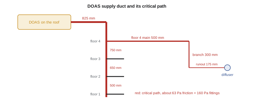
The components dominate: the energy recovery wheel, two filter banks, the wet cooling coil, the heating coil, a sound attenuator, the outdoor air intake and the diffuser with its balancing damper together account for about 850 Pa. Filters are taken at mid-life, between their clean and final pressure drops, so that the fan is selected for the condition it will operate in most of the time; the controls raise fan speed as the filters load. Adding an allowance of 60 Pa for system effect gives a required total pressure of about 1,130 Pa.
System effect
Fans are rated by their makers in standard test arrangements with long, straight ducts at inlet and outlet. A fan installed with an elbow right at its inlet, or discharging into a plenum, performs worse than its rating because the flow entering or leaving it is distorted. The loss is called system effect, and published system effect factors allow it to be estimated. The best remedy is to avoid it with good fan inlet and outlet arrangements; the next best is to allow for it, as the program does. Ignoring it is one of the most common reasons systems fail to deliver their design airflow.
Selecting the fan
Fan power is the airflow times the total pressure divided by the overall efficiency of the fan, motor and drive. The program shows that at an overall efficiency of 0.65, a reasonable figure for a direct-drive plenum fan with an electronically commutated or premium-efficiency motor on a variable-frequency drive, the DOAS supply fan needs about 7.8 kW. Several smaller fans in a fan array, common in modern air handlers, provide redundancy: if one fails the others speed up. The hospital requires redundancy for the urgent care DOAS and the imaging units, and the general DOAS has a fan array of four fans sized so that three can carry the building at reduced pressure.
The fan laws describe how a given fan's performance scales with speed, and they predict the operating point when the system's resistance varies with the square of flow, so that the system curve passes through the origin. The fan's operating point is where its curve crosses the system curve. Energy codes limit fan power, either directly as an allowance in watts per unit airflow or through the energy performance of the whole building; this fan's 1.7 W per L/s is within typical limits for a DOAS with energy recovery and high-efficiency filtration.
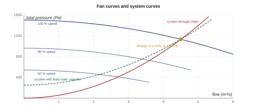
Real systems often do not follow the simple fan laws. If the DOAS supplies variable-volume ventilation terminals, as it does in the offices where occupancy sensors reduce airflow to empty rooms, the controls hold a static pressure in the duct, and the system curve has a constant term. The power saving at reduced flow is then less than the cube law predicts. That is why Lesson 10's static pressure reset matters: lowering the setpoint as demand falls moves the system curve back toward the origin.
Leakage, construction and exhaust
Ducts leak at their seams and joints, and leakage wastes fan energy and, in a DOAS, conditioned outdoor air that never reaches the rooms. Duct construction standards classify ducts by pressure and specify sealing; energy codes and owners' specifications set leakage limits, usually as a leakage class or an allowable fraction of design flow at a test pressure, and require sections of duct to be tested before the ceilings close. For the health centre the specification calls for all supply ducts to be sealed to the highest class and for at least a quarter of the supply ductwork, chosen by the engineer, to be pressure tested. A DOAS that loses 5 percent of its air in the ceiling loses 5 percent of its ventilation and dehumidification as well.
The exhaust system mirrors the supply. General exhaust from toilets, soiled utility rooms, the urgent care waiting room and the isolation room is collected in separate risers to exhaust fans on the roof; the general exhaust passes through the energy recovery wheel, while exhaust from the isolation room and soiled rooms has its own fan and discharges well away from intakes. Intake and exhaust separation on the roof is checked against code minimum distances and, for the isolation room exhaust, against the hospital's requirement for a high discharge velocity. The return paths in the DOAS design are short: each room's fan coil recirculates its own air, so there is no central return duct at all, which saves a great deal of ceiling space.
Duct design also has to coordinate with everything else in the ceiling. Sprinkler mains, cable trays, plumbing and medical gas pipes all compete for the same 600 to 800 mm above the ceiling tiles. The mechanical engineer usually gets first claim on space for the largest ducts, but only if the ducts are laid out early in a coordinated three-dimensional model. The DOAS's small ducts are one of its quiet advantages: they leave room for everything else.
Air distribution in the rooms
Diffusers are selected for the airflow, the throw and the noise. Throw is the distance from the diffuser at which the jet's velocity falls to a terminal value, often 0.25 m/s, and it should carry the air across the occupied zone without causing draughts. In the examination rooms, where gowned patients are sensitive to air movement, the diffusers are placed away from the examination table and selected for low velocities at the table. The air distribution performance index, ADPI, measures the fraction of points in the occupied zone that meet draught criteria, and manufacturers' data link it to the ratio of throw to room length.
Worked problem
Velocity and friction in a branch
A round branch carries 0.28 m³/s in a 300 mm galvanized duct. Using the program's air properties, find the velocity and estimate whether the friction gradient is near the target of 0.8 Pa/m.
Show solution
- Area: \(\pi \times 0.3^2/4 = 0.0707\) m²; velocity \(0.28/0.0707 = 3.96\) m/s.
- Reynolds number: \(1.18 \times 3.96 \times 0.3/1.82\times 10^{-5} = 7.7 \times 10^4\).
- With f about 0.0205 from Colebrook, \(\Delta p/L = 0.0205/0.3 \times 1.18 \times 3.96^2/2 = 0.63\) Pa/m.
Answer: The branch runs at about 4.0 m/s and 0.63 Pa/m, within the target. A 250 mm duct would exceed it, at about 1.6 Pa/m, which is why the program chose 300 mm.
Common mistakes
MistakeSelecting the fan for clean filters.
InsteadSelect at mid-life filter pressure and let the controls compensate as filters load.
MistakeIgnoring system effect at fan inlets and outlets.
InsteadDesign good fan connections and allow for the remaining effect.
MistakeAssuming the cube law applies to every system.
InsteadA fixed static pressure setpoint adds a constant term; reset it to save energy.
MistakeSizing ducts above quiet rooms for the same velocity as in shafts.
InsteadApply lower velocity limits and attenuation where noise matters.
MistakeConcentrating on duct length and forgetting fittings.
InsteadFittings usually cause more loss than straight duct; choose them carefully.
Summary and key terms
- Total pressure is static plus velocity pressure; fans add it, friction and fittings remove it.
- Equal friction is simple; static regain balances long mains; the T-method optimizes cost.
- The DOAS critical path loses about 63 Pa in duct, 160 Pa in fittings and 850 Pa in components.
- With a 60 Pa system effect allowance, the fan needs about 1,130 Pa and about 7.8 kW.
- Fan laws hold for system curves through the origin; static pressure control changes that.
- Diffusers are chosen for throw, draught and noise, with care around examination tables.
- Static pressure
- The pressure exerted by air on the walls of a duct, independent of its motion.
- Velocity pressure
- The kinetic energy of air per unit volume, ρv²/2.
- Equal friction method
- Duct sizing with the same friction loss per unit length in every section.
- Static regain method
- Duct sizing in which static pressure regained at velocity reductions offsets downstream friction.
- Critical path
- The path from fan to terminal with the highest total pressure loss.
- System effect
- The loss of fan performance caused by non-ideal inlet and outlet conditions.
- Fan array
- Several smaller fans operating in parallel in one air handler.
- Throw
- The distance from a diffuser at which the air velocity falls to a stated terminal value.
Practice problems
Work each problem on paper first, then reveal the answer to check.
Find the velocity pressure of air at 1.18 kg/m³ moving at 8 m/s.
Show answer
\(1.18 \times 64/2 = 37.8\) Pa.
An elbow has C = 0.25 in a duct at 7 m/s. Find its loss.
Show answer
\(0.25 \times 1.18 \times 49/2 = 7.2\) Pa.
A fan delivers 4.5 m³/s at 1,130 Pa with an overall efficiency of 0.60. Find its input power.
Show answer
\(4.5 \times 1130/0.60 = 8.5\) kW.
If the fan in the program slows to 70 percent speed on a system curve through the origin, estimate its power.
Show answer
\(0.7^3 \times 7.8 = 2.7\) kW.
Why are filters taken at mid-life for fan selection?
Show answer
It represents typical operation; the controls raise fan speed as filters load toward their final pressure.
Lesson quiz · 5 questions
Score 60% or more to complete this lesson.
Create a free account to save your progress, take quizzes and earn a certificate.