
MEC-430 · Lesson 4 of 12 · 22 min
Envelope heat transfer and heating loads
The design heating load is the rate at which heat must be supplied to keep the building at its indoor design temperature when the outdoor air is at the heating design temperature. It sets the size of the energy transfer station's heating exchanger, the heating water flow, the pipes and the terminal units, and in Winnipeg it is a serious number: the January 2.5 percent design temperature in Appendix C of the National Building Code is about −33 °C. This lesson calculates the health centre's heating load the way a designer does at the concept stage, using the envelope the architect has proposed, and shows where the heat goes.
Design temperatures
Heating design temperatures are statistics, not records. The National Building Code's January design temperatures are the temperatures that are equalled or exceeded in 97.5 percent and 99 percent of the hours in January, so the 2.5 percent value is colder than all but about 19 hours in a typical January. The building will occasionally see colder weather, but for only a few hours, during which the building's thermal mass and the margin in the equipment carry it through. Designing for the record low would oversize everything for conditions that almost never occur. The indoor design temperature is 22 °C for occupied areas, with the examination rooms able to reach 26 °C as Lesson 3 required.
Conduction through the envelope
Steady conduction through each envelope element is its area times its overall heat transfer coefficient times the indoor-outdoor temperature difference. Each U-value comes from the thermal resistances in series that MEC-340 taught you to add, including the inside and outside surface films:
Real walls are not uniform layers. Steel studs, floor slab edges that pass through the insulation, shelf angles that support brick, balcony connections and the junctions around windows all conduct heat around the insulation. These are thermal bridges, and in modern well-insulated buildings they can add a quarter or more to the heat loss of the opaque walls. Energy codes now require them to be counted. The method is to add the heat flow through linear bridges, ψ times their length, and point bridges, χ times their number, to the clear-field loss:
For the concept design Tomás uses effective U-values that already include typical bridging for the details the architect has proposed: 0.21 W/m²K for the opaque walls, which is an effective thermal resistance of about RSI 4.8, 1.60 W/m²K for the windows including their frames, and 0.14 W/m²K for the roof. The slab-on-grade floor loses heat mainly through its edge, so its loss is expressed as a coefficient F per metre of perimeter, here 0.60 W/(m K) for an insulated edge.
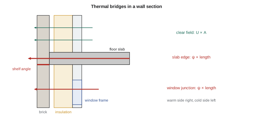
Air leakage and ventilation
Outdoor air entering the building must be heated to room temperature. There are two very different flows. Infiltration is uncontrolled leakage through cracks and openings, driven by wind and stack effect. Ventilation is the deliberate supply of outdoor air through the mechanical system. In a tall, well-sealed building with a mechanical system that supplies slightly more air than it exhausts, infiltration is small most of the time, though it rises at the lower floors in very cold weather because of stack effect. Tomás uses a design infiltration rate of 0.05 L/s per m² of above-grade envelope area, appropriate for a pressurized building with a tested air barrier. For older or leakier buildings designers use rates several times higher, or estimate leakage from a blower-door test.
Ventilation air is handled differently, because it passes through the dedicated outdoor air unit. There an energy recovery wheel transfers heat from the warm exhaust to the cold incoming air before the heating coil warms it the rest of the way to the supply temperature of 18 °C. The recovery effectiveness, the ratio of the actual temperature rise to the largest possible, is about 0.70 for a good wheel. The ventilation heating load is then the load on the coil downstream of the wheel.
# Design heating load for the Riverside Community Health Centre
SITE = 'ca'
d = {'ca': dict(city='Winnipeg', to=-33.0, src='January 2.5 % design temperature'),
     'us': dict(city='Minneapolis', to=-27.0, src='99.6 % heating design temperature')}[SITE]
ti = 22.0; dT = ti - d['to']
perim, height, wwr, roof = 160.0, 16.8, 0.35, 1500.0
wall_gross = perim*height; win = wwr*wall_gross; opaque = wall_gross - win
# effective U-values including thermal bridging at slab edges, shelf angles and window interfaces
items = [('opaque walls', opaque, 0.21), ('windows', win, 1.60), ('roof', roof, 0.14)]
print(f"{d['city']}: indoor {ti:.0f} C, outdoor {d['to']:.0f} C ({d['src']}), dT = {dT:.0f} K\n")
print("Component           area (m2)    U (W/m2K)   UA (W/K)   load (kW)")
UA = 0
for n, a, u in items:
    UA += a*u; print(f"{n:18s} {a:9.0f}     {u:6.2f}      {a*u:7.0f}    {a*u*dT/1000:7.1f}")
F = 0.60                                             # slab-edge heat loss per metre of perimeter, W/(m K)
UA += F*perim; print(f"{'slab edge':18s} {perim:9.0f} m   F {F:.2f}      {F*perim:7.0f}    {F*perim*dT/1000:7.1f}")
leak = 0.05*(wall_gross + roof)                      # infiltration, L/s, pressurized building
c_air = 1.20*1.006                                   # W per (L/s K) at the site density
UA_inf = c_air*leak; print(f"{'infiltration':18s} {leak:9.0f} L/s             {UA_inf:7.0f}    {UA_inf*dT/1000:7.1f}")
env = (UA + UA_inf)*dT/1000
print(f"Envelope and infiltration: {env:.1f} kW  ({(UA + UA_inf)*dT/6000:.0f} W/m2)")
# ventilation: 4,500 L/s outdoor air through an energy recovery wheel, effectiveness 0.70, heated to 18 C supply
Qoa, eff, ts = 4500.0, 0.70, 18.0
t_rec = d['to'] + eff*(ti - d['to'])
vent = c_air*Qoa*(ts - t_rec)/1000
print(f"Ventilation: {Qoa:.0f} L/s, after recovery {t_rec:.1f} C, heated to {ts:.0f} C -> {vent:.1f} kW")
print(f"  without heat recovery it would be {c_air*Qoa*(ts - d['to'])/1000:.1f} kW")
tot = env + vent
print(f"Total design heating load: {tot:.1f} kW; with 10 % for morning warm-up and pipe losses: {1.1*tot:.0f} kW")
print(f"Shares: windows {100*win*1.6*dT/1000/tot:.0f} %, ventilation {100*vent/tot:.0f} %, all other {100*(tot - win*1.6*dT/1000 - vent)/tot:.0f} %")
if SITE == 'us':
print(f"US units: {d['to']*1.8+32:.0f} F design, total {tot*3412:,.0f} Btu/h; with 10 %: {1.1*tot*3412:,.0f} Btu/h")Winnipeg: indoor 22 C, outdoor -33 C (January 2.5 % design temperature), dT = 55 K Component area (m2) U (W/m2K) UA (W/K) load (kW) opaque walls 1747 0.21 367 20.2 windows 941 1.60 1505 82.8 roof 1500 0.14 210 11.6 slab edge 160 m F 0.60 96 5.3 infiltration 209 L/s 253 13.9 Envelope and infiltration: 133.7 kW (22 W/m2) Ventilation: 4500 L/s, after recovery 5.5 C, heated to 18 C -> 67.9 kW without heat recovery it would be 277.1 kW Total design heating load: 201.6 kW; with 10 % for morning warm-up and pipe losses: 222 kW Shares: windows 41 %, ventilation 34 %, all other 25 %
Reading the result
For Winnipeg the program gives a design heating load of about 202 kW at a 55 K temperature difference. The windows, although they are only 35 percent of the wall area, account for about 41 percent of the total. Ventilation after energy recovery accounts for about a third. Without the recovery wheel the ventilation load alone would be 277 kW, more than the whole building's load with it. Those two facts point to the two places where the envelope and system designs matter most in a cold climate: the glazing and the heat recovery.
The opaque walls and roof, which take up most of the envelope area, contribute only about 15 percent of the load between them. This is a common pattern in modern buildings, and it explains why energy codes in cold climates have tightened window requirements and introduced limits on the window-to-wall ratio. Kofi points out that triple glazing with a frame U-value near 1.0 W/m²K would cut the design load by about 30 kW, reduce the cold-window effect on comfort, and allow the perimeter heating to be smaller. Lesson 11 tests the annual energy effect.
| Component | Share of design load | Main design lever |
|---|---|---|
| Windows | about 41 % | glazing and frame U-value, window area |
| Ventilation after recovery | about one third | recovery effectiveness, outdoor air rate |
| Opaque walls and roof | about 15 % | insulation and thermal bridging |
| Infiltration | about 7 % | air barrier quality and building pressure |
| Slab edge | about 3 % | edge insulation |
Allowances and what to leave out
A design heating load calculation deliberately leaves out internal gains from people, lights and equipment and from the sun, because the worst case is a cold night or weekend when they are absent. It also leaves out the thermal storage of the structure, which would reduce the peak. It does add allowances where they are justified. The program adds 10 percent for morning warm-up after night setback and for heat lost from piping in unheated spaces, giving a design load of about 222 kW. The warm-up allowance depends on how deep the setback is and how quickly the building must recover; for a clinic that opens at 07:00 with staff arriving earlier, a modest setback of 4 K and a two-hour recovery period suit the allowance chosen.
Heating loads are also needed room by room, to size each terminal unit. Perimeter rooms with large windows can need 60 to 100 W/m² of floor area, interior rooms almost nothing, and corner rooms more than either. A clinic examination room on a north corner, with a gowned patient at 26 °C, is the worst case on each floor and gets its own check. Interior rooms, which in winter still have internal gains, may need cooling while the perimeter needs heating, and the system must be able to do both at once. Lesson 6 compares systems with that requirement in mind.
Checking the result
A calculated load should always be compared with experience. The envelope and infiltration part of the load works out to about 20 to 22 W per square metre of floor, and the whole load, including ventilation, to about 30 to 34 W/m². That agrees well with the rule-of-thumb densities used in Lesson 1, which suggests that the architect's envelope is typical of a good modern building rather than exceptional, and that the early space allowances for heating were sound. A result far outside the expected range is a reason to look for an error, such as a window area entered in square feet or a design temperature with the wrong sign, before it is a reason to believe the building is unusual.
At design development the concept calculation is replaced by a room-by-room calculation in load software, which handles each orientation, corner and room type and keeps the input in one place for later changes. The software is only as good as its input. The engineer checks its totals against a hand calculation like this one, and when the architect changes the glazing or the outdoor air rate changes, both are revised. Many of the worst errors in practice come not from the method but from stale inputs: a load run done before the window area grew, or before a room changed from storage to procedure room.
Heating terminal units
With heating water at 55 °C supply and 40 °C return, terminal units must be larger than they would be at the traditional 82/71 °C. A radiant panel or fin-tube element's output depends roughly on the mean water temperature minus the room temperature raised to a power a little above 1, so dropping the mean water temperature from 77 °C to 47.5 °C reduces the temperature difference from 55 K to 25.5 K and the output per metre by more than half. The design compensates with longer elements, ceiling radiant panels in the perimeter zones and heating coils sized for the low temperature in the fan coils. The gain is a cool return, which Northgate values, and the ability to run from heat pumps later without changing the building.
Worked problem
Perimeter heating for a corner room
A north-west corner examination room has 9 m² of window (U = 1.60), 14 m² of opaque wall (U = 0.21) and 4 m of slab-edge-equivalent bridging at ψ = 0.3 W/(m K). It is held at 26 °C with the outdoor air at −33 °C. Find the conduction heat loss.
Show solution
- \(\Delta T = 26 - (-33) = 59\) K.
- Window: \(9 \times 1.60 \times 59 = 850\) W. Wall: \(14 \times 0.21 \times 59 = 173\) W. Bridges: \(4 \times 0.3 \times 59 = 71\) W.
- Total conduction: about 1,094 W, before any share of the ventilation or infiltration load.
Answer: The room needs about 1.1 kW of perimeter heating, nearly 80 percent of it through the window. At 55/40 °C water the radiant ceiling panel above the window wall must be sized for this load at a mean water temperature of about 47 °C.
Common mistakes
MistakeDesigning for the record low temperature.
InsteadUse the published design temperature; mass and margins carry the rare colder hours.
MistakeUsing clear-field wall U-values.
InsteadInclude thermal bridges at slab edges, shelf angles and window junctions.
MistakeCounting internal gains in the design heating load.
InsteadLeave them out; the design case is an unoccupied cold night.
MistakeTreating ventilation and infiltration as one flow.
InsteadVentilation passes through the recovery wheel and coil; infiltration does not.
MistakeSizing low-temperature terminals with high-temperature output ratings.
InsteadDerate outputs for the actual mean water temperature.
Summary and key terms
- Design heating load is the heat needed at the design temperature, without internal or solar gains.
- Conduction is UA times the temperature difference, with U including thermal bridging.
- Windows give about 41 percent of the health centre's design load and ventilation about a third.
- Energy recovery cuts the ventilation load by about three quarters.
- With a 10 percent warm-up and piping allowance the design load is about 222 kW.
- Low-temperature heating needs larger terminals but returns cool water to the district.
- Heating design temperature
- A statistical outdoor temperature, exceeded in a stated large fraction of hours, used to size heating equipment.
- Thermal bridge
- A part of the envelope where heat bypasses the insulation, such as a slab edge or a fastener.
- Linear transmittance
- The extra heat flow per metre of a linear thermal bridge per kelvin, symbol ψ.
- Effective U-value
- An overall heat transfer coefficient that includes the effect of thermal bridges.
- Infiltration
- Uncontrolled leakage of outdoor air into a building.
- Energy recovery effectiveness
- The ratio of the actual heat transferred by a recovery device to the maximum possible.
- Stack effect
- Pressure differences caused by the density difference between warm indoor and cold outdoor air over the building height.
- Night setback
- Lowering the heating setpoint when a building is unoccupied, which requires warm-up capacity.
Practice problems
Work each problem on paper first, then reveal the answer to check.
A wall of 200 m² has U = 0.25 W/m²K. Find its heat loss at a 50 K difference.
Show answer
2.5 kW.
What is the infiltration load of 300 L/s at a 55 K difference?
Show answer
\(1.21 \times 10^{-3} \times 300 \times 55 = 20.0\) kW.
Outdoor air at −30 °C passes a wheel of effectiveness 0.75 with exhaust at 22 °C. Find the air temperature after the wheel.
Show answer
\(-30 + 0.75 \times 52 = 9\) °C.
In the program, what would the design load be with windows at U = 1.0?
Show answer
About 34 percent less window loss: roughly 31 kW lower.
Why are interior rooms a concern even in winter?
Show answer
They may need cooling at the same time as perimeter rooms need heating.
Lesson quiz · 5 questions
Score 60% or more to complete this lesson.
Create a free account to save your progress, take quizzes and earn a certificate.