
MEC-430 · Lesson 2 of 12 · 23 min
Psychrometrics for HVAC design
Every air-side decision in the health centre depends on the properties of moist air. How cold must the outdoor air be cooled to dry it enough? How much water will drain from the coil? How much latent load can the ventilation air absorb? Thermodynamics II introduced ideal-gas mixtures and the psychrometric chart. This lesson uses them the way a designer does: with the relations published by ASHRAE, corrected for the site's barometric pressure, and applied to the dedicated outdoor air unit that will supply the building's ventilation.
The properties a designer uses
Moist air is treated as a mixture of dry air and water vapour, both ideal gases. Its state is fixed by three independent properties, one of which is usually the total pressure. The quantities used in design are the dry-bulb temperature; the humidity ratio W, the mass of water vapour per unit mass of dry air; the relative humidity, the ratio of the vapour's partial pressure to the saturation pressure at the same temperature; the dew-point temperature, at which the air would become saturated if cooled at constant humidity ratio; the thermodynamic wet-bulb temperature; the specific enthalpy h per kilogram of dry air; and the specific volume per kilogram of dry air. All are per unit mass of dry air because dry air passes through a process unchanged while water is added or removed.
Here \(p_w\) is the vapour partial pressure and p the total pressure. The saturation pressure of water comes from a correlation such as the Hyland–Wexler equation that ASHRAE publishes. The wet-bulb temperature links to W through an energy balance on an adiabatic saturation process, which is how a designer turns a design wet bulb from a climate table into a humidity ratio.
where \(t^*\) is the wet-bulb temperature and \(W_s^*\) the saturation humidity ratio at \(t^*\).
Correcting for altitude
Printed psychrometric charts are usually drawn for standard sea-level pressure, 101.325 kPa. Winnipeg sits at about 240 to 260 m above sea level, where the average barometric pressure is about 98.5 kPa. The difference looks small, but humidity ratio depends on \(p - p_w\), so at the same dew point the air holds about 3 percent more water by mass than the sea-level chart suggests, and the air is about 3 percent less dense. A careful designer calculates with the site pressure rather than reading a sea-level chart. For cities at high elevations, such as Calgary or Denver, the correction is far larger and charts are published for those pressures.
Design conditions
Climate tables give the conditions to design for. For cooling there are two kinds. The dry-bulb design condition, with its mean coincident wet bulb, sets the sensible load and the coil's total capacity. For Winnipeg the table values used here are 30 °C dry bulb with a 23 °C wet bulb, from Appendix C of the National Building Code. These are rounded values for a teaching example; real projects take them from the current tables. The second kind is the dehumidification design condition, a dew point with its mean coincident dry bulb, which is the condition at which outdoor air carries the most moisture. It usually occurs on a muggy, overcast day that is not especially hot. A system that handles a large amount of outdoor air, as this one does, must be checked at both, because the dehumidification condition sets the latent load and often the coil depth.
Coil processes
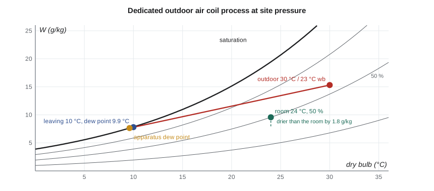
A cooling coil whose surface is below the air's dew point both cools and dehumidifies it. On the chart the process is close to a straight line from the entering state toward a point on the saturation curve called the apparatus dew point, which approximates the effective coil surface temperature. The air does not reach that point; the fraction of the way it falls short is called the bypass factor, as though part of the air passed through the coil untouched. Deep coils with closely spaced fins have small bypass factors. The energy removed is the enthalpy difference times the dry-air mass flow, and the water removed is the humidity ratio difference times the same flow.
Splitting the total into sensible and latent parts gives the coil's sensible heat ratio. A coil with a low SHR is doing mostly drying. Heating, humidifying and mixing are the other common processes. Mixing two airstreams adiabatically puts the mixed state on the straight line between them, at the mass-weighted position. Steam humidification moves the state almost vertically on the chart, adding moisture with very little change in dry-bulb temperature.
The dedicated outdoor air unit
The building's ventilation will come from a dedicated outdoor air system, a unit that conditions only outdoor air and delivers it to every room. Lesson 3 sets the rate at 4,500 L/s. In summer the unit's job is not only to cool that air but to dry it enough that it absorbs all the moisture the occupants give off, so that the room terminal units, fan coils in this design, can run dry. A dry fan coil needs no condensate drain, which matters in a clinic where wet drain pans in ceilings are an infection control concern.
# Psychrometrics for the dedicated outdoor air unit at summer design (ASHRAE-style relations)
import math
SITE = 'ca'
P = {'ca': 98.5, 'us': 98.3}[SITE]                 # site barometric pressure, kPa
odb, owb = {'ca': (30.0, 23.0), 'us': (33.0, 23.0)}[SITE]
def psat(t):                                         # saturation pressure over water, kPa (Hyland-Wexler form)
    T = t + 273.15
    return math.exp(-5.8002206e3/T + 1.3914993 - 4.8640239e-2*T + 4.1764768e-5*T*T
                    - 1.4452093e-8*T**3 + 6.5459673*math.log(T))/1000
def W_from_pv(pv): return 0.621945*pv/(P - pv)
def W_from_wb(tdb, twb):
    Ws = W_from_pv(psat(twb))
    return ((2501 - 2.326*twb)*Ws - 1.006*(tdb - twb))/(2501 + 1.86*tdb - 4.186*twb)
def h(tdb, W): return 1.006*tdb + W*(2501 + 1.86*tdb)          # kJ/kg dry air
def dew(W):
    pv = W*P/(0.621945 + W); lo, hi = -40.0, 60.0
    for _ in range(60):
        mid = (lo + hi)/2
        lo, hi = (mid, hi) if psat(mid) < pv else (lo, mid)
    return (lo + hi)/2
def v(tdb, W): return 0.287042*(tdb + 273.15)*(1 + 1.607858*W)/P  # m3/kg dry air
Wo = W_from_wb(odb, owb); ho = h(odb, Wo)
print(f"Outdoor design {odb:.0f} C db / {owb:.0f} C wb at {P} kPa: W = {1000*Wo:.2f} g/kg, h = {ho:.1f} kJ/kg, "
      f"dew point {dew(Wo):.1f} C, RH {100*(Wo*P/(0.621945 + Wo))/psat(odb):.0f} %")
tr, rh = 24.0, 0.50
Wr = W_from_pv(rh*psat(tr)); hr = h(tr, Wr)
print(f"Room 24 C, 50 % RH: W = {1000*Wr:.2f} g/kg, h = {hr:.1f} kJ/kg, dew point {dew(Wr):.1f} C")
# DOAS coil: 4,500 L/s of outdoor air cooled and dehumidified to a 10.5 C dew point, leaving nearly saturated
Q = 4.5                                               # m3/s at outdoor conditions
m = Q/v(odb, Wo)                                     # kg/s dry air
tl = 11.0; Wl = W_from_pv(psat(10.5)); hl = h(tl, Wl)
qt = m*(ho - hl); qs = m*1.006*(odb - tl) + m*Wo*1.86*(odb - tl)
cond = m*(Wo - Wl)
print(f"DOAS coil: {m:.2f} kg/s, leaving {tl:.1f} C with W = {1000*Wl:.2f} g/kg (dew point 10.5 C)")
print(f"  total {qt:.0f} kW, sensible {qs:.0f} kW, latent {qt - qs:.0f} kW, coil SHR {qs/qt:.2f}, condensate {cond*3600:.0f} kg/h")
# How much room latent load can the dry outdoor air absorb when supplied at the room humidity ratio deficit?
lat = m*(Wr - Wl)*2501
print(f"  supplied drier than the room by {1000*(Wr - Wl):.2f} g/kg, the DOAS air absorbs {lat:.0f} kW of room latent load")
people_lat = 400*0.055
print(f"  latent load from 400 occupants at 55 W each: {people_lat:.0f} kW -> {'covered' if lat >= people_lat else 'not covered'}")
Wreq = Wr - people_lat/(m*2501)
print(f"  to absorb {people_lat:.0f} kW the supply must leave at W = {1000*Wreq:.2f} g/kg, a dew point of {dew(Wreq):.1f} C")
tl = 10.0; Wl = Wreq; hl = h(tl, Wl)
qt = m*(ho - hl); qs = m*1.006*(odb - tl) + m*Wo*1.86*(odb - tl); cond = m*(Wo - Wl)
print(f"Revised coil, leaving {tl:.1f} C: total {qt:.0f} kW, sensible {qs:.0f} kW, latent {qt - qs:.0f} kW, SHR {qs/qt:.2f}, condensate {cond*3600:.0f} kg/h")
# Apparatus dew point and bypass factor for the coil line (straight line on the chart through the leaving state)
adp = None
for i in range(1, 400):
    t = tl - i*0.02; Ws = W_from_pv(psat(t))
    slope_line = (Wo - Wl)/(odb - tl); W_line = Wl - slope_line*(tl - t)
    if Ws <= W_line: adp = t; break
BF = (tl - adp)/(odb - adp)
print(f"  apparatus dew point {adp:.1f} C, bypass factor {BF:.2f}")
if SITE == 'us':
    print(f"US units: outdoor {odb*1.8+32:.0f} F db / {owb*1.8+32:.0f} F wb, coil {qt*3412/12000:.0f} tons, leaving {tl*1.8+32:.1f} F, "
f"{Q*2118.9:,.0f} cfm, condensate {cond*3600*2.2046/8.34:.0f} US gal/h")Outdoor design 30 C db / 23 C wb at 98.5 kPa: W = 15.31 g/kg, h = 69.3 kJ/kg, dew point 20.2 C, RH 56 % Room 24 C, 50 % RH: W = 9.57 g/kg, h = 48.5 kJ/kg, dew point 12.9 C DOAS coil: 4.97 kg/s, leaving 11.0 C with W = 8.12 g/kg (dew point 10.5 C) total 188 kW, sensible 98 kW, latent 90 kW, coil SHR 0.52, condensate 129 kg/h supplied drier than the room by 1.45 g/kg, the DOAS air absorbs 18 kW of room latent load latent load from 400 occupants at 55 W each: 22 kW -> not covered to absorb 22 kW the supply must leave at W = 7.80 g/kg, a dew point of 9.9 C Revised coil, leaving 10.0 C: total 197 kW, sensible 103 kW, latent 94 kW, SHR 0.52, condensate 134 kg/h apparatus dew point 9.6 C, bypass factor 0.02
The first attempt leaves the coil at 11 °C with a 10.5 °C dew point, a common rule-of-thumb leaving condition. The program shows that this air, about 1.45 g/kg drier than the room, absorbs only 18 kW of latent load, less than the 22 kW from 400 occupants. To absorb it all, the air must leave with a humidity ratio of 7.80 g/kg, a dew point of 9.9 °C. The revised coil, leaving at 10 °C and very nearly saturated, has a total load of about 197 kW. On a Winnipeg design day its sensible heat ratio is 0.52: half or more of its work is drying. Winnipeg's design wet bulb is high relative to its dry bulb, which makes the outdoor air humid at design and the coil's latent share large.
The leaving state is close to saturation, and the bypass factor the program finds is only a few hundredths. That is a deep coil: in practice eight rows or more with tight fin spacing, a large face area to keep the face velocity near 2.5 m/s so that condensate does not blow off, and a chilled water supply cold enough to reach a 9 to 10 °C apparatus dew point. Lesson 8 checks that the district's 5.5 °C chilled water can do it. Coil selection software from manufacturers does the detailed rating; the designer's job is to set the leaving condition correctly and to check that the selection meets it.
Worked problem
Condensate and the drain
Find the condensate flow from the revised DOAS coil at the Winnipeg design condition, given 4.97 kg/s of dry air, an entering humidity ratio of 15.31 g/kg and a leaving humidity ratio of 7.80 g/kg.
Show solution
- \(\dot m_w = 4.97 \times (0.01531 - 0.00780) = 0.0373\) kg/s.
- Per hour: \(0.0373 \times 3600 = 134\) kg/h, about 134 L/h.
- Over a ten-hour humid day this is more than a cubic metre of water.
Answer: About 134 L/h of condensate leaves the coil. It must drain through a trapped connection sized for the fan's negative pressure at the coil, and it is clean enough to be worth reusing, for example in cooling tower makeup at the district plant or for irrigation.
Supply air and room lines
For a room served by conditioned air, the supply state must lie on the room's process line, the line through the room state with a slope set by the room's sensible heat ratio. The airflow then follows from the sensible load and the temperature difference between supply and room.
The factor 1.21 kW per m³/s per kelvin assumes air at about 1.20 kg/m³, which suits the site; at sea level the usual factor is about 1.23. In inch-pound units the familiar form is \(\dot Q_s = 1.08 \times \text{cfm} \times \Delta T\) in Btu/h, also for sea-level air, and it should be reduced at altitude. Similar factors exist for latent heat, 3,010 kW per m³/s per unit humidity ratio difference in kg/kg, and for total heat with enthalpy differences.
| Quantity | SI form (site air) | Inch-pound form (sea level) |
|---|---|---|
| Sensible | 1.21 × V (m³/s) × ΔT (K) kW | 1.08 × cfm × ΔT (°F) Btu/h |
| Latent | 3,010 × V × ΔW (kg/kg) kW | 0.68 × cfm × ΔW (grains/lb) Btu/h |
| Total | 1.20 × V × Δh (kJ/kg) kW | 4.5 × cfm × Δh (Btu/lb) Btu/h |
Winter humidity
In winter the outdoor air holds almost no water. At −30 °C saturated air has a humidity ratio of about 0.3 g/kg, and when it is heated to 22 °C its relative humidity falls below 2 percent. The occupants add moisture, but in a building with 4,500 L/s of outdoor air the indoor humidity in a cold spell will fall to 10 or 15 percent without humidification. The hospital requires a minimum relative humidity in some areas, and the energy recovery wheel in the dedicated outdoor air unit helps by transferring some moisture from the exhaust to the supply. Lesson 3 discusses the limits, and the humidifier sizing follows from the same humidity ratio balance used here.
Common mistakes
MistakeUsing a sea-level chart for a site several hundred metres up.
InsteadCalculate with the site barometric pressure.
MistakeDesigning a large outdoor air coil only at the dry-bulb cooling condition.
InsteadCheck the dehumidification design condition too; it often sets the coil.
MistakeChoosing the DOAS leaving condition by habit.
InsteadSet it from the room latent load the outdoor air must absorb.
MistakeUsing 1.23 or 1.08 at any elevation.
InsteadCorrect the air factors for the actual air density.
MistakeAssuming a coil can leave air at the apparatus dew point.
InsteadReal coils fall short by the bypass factor; very low leaving dew points need deep coils and cold water.
Summary and key terms
- Moist air properties are expressed per kilogram of dry air; three independent properties fix the state.
- Calculate at site pressure; at 250 m the correction is about 3 percent.
- Check outdoor air coils at both the dry-bulb and the dehumidification design conditions.
- The DOAS must leave dry enough to absorb the occupants' latent load: a 9.9 °C dew point here.
- The revised coil handles about 195 to 197 kW, with half or more of it latent.
- Air factors such as 1.21 kW per m³/s per K depend on air density.
- Humidity ratio
- Mass of water vapour per unit mass of dry air.
- Dew-point temperature
- The temperature at which moist air becomes saturated when cooled at constant humidity ratio.
- Apparatus dew point
- The point on the saturation curve toward which a cooling coil process line is directed, approximating the effective coil surface temperature.
- Bypass factor
- The fraction of the distance from the entering state to the apparatus dew point that the leaving air falls short.
- Sensible heat ratio
- The ratio of sensible to total heat in a load or process.
- Dehumidification design condition
- A design dew point with its mean coincident dry bulb, used to size equipment for moisture removal.
- Dedicated outdoor air system
- A system that conditions and delivers only outdoor air, separately from the room heating and cooling.
- Room process line
- The line on the chart through the room state along which supply states must lie to meet a given sensible heat ratio.
Practice problems
Work each problem on paper first, then reveal the answer to check.
At 98.5 kPa, what is the humidity ratio of air with a vapour pressure of 1.5 kPa?
Show answer
\(0.621945 \times 1.5/97.0 = 9.62\) g/kg.
Find the enthalpy of air at 24 °C with W = 9.57 g/kg.
Show answer
\(1.006 \times 24 + 0.00957(2501 + 1.86 \times 24) = 48.5\) kJ/kg.
A room needs 12 kW of sensible cooling with supply air at 13 °C and a room at 24 °C. Find the airflow at site density.
Show answer
\(12/(1.21 \times 11) = 0.90\) m³/s.
Why is a dry fan coil attractive in a clinic?
Show answer
It needs no condensate drain or wet pan in the ceiling, which removes a source of microbial growth and leaks.
In the program, what leaving dew point would be needed if the building had 500 occupants?
Show answer
Lower: about 9.2 °C, because the outdoor air must absorb 27.5 kW of latent load.
Lesson quiz · 5 questions
Score 60% or more to complete this lesson.
Create a free account to save your progress, take quizzes and earn a certificate.