
MEC-430 · Lesson 10 of 12 · 20 min
Controls and sequences of operation
A well-designed HVAC system can still use far more energy than it should, and keep its occupants uncomfortable, if it is badly controlled. Studies of existing buildings repeatedly find that a large share of HVAC energy is wasted by controls: setpoints fighting each other, equipment running when nobody is there, fixed pressure setpoints far above what the system needs, simultaneous heating and cooling. The designer's tool against this is the sequence of operations, a written description of exactly how each system is to be controlled. This lesson writes the main sequences for the health centre and introduces the standard practice that has made them much better in recent years.
Sequences of operation
A sequence of operations states, for each piece of equipment, when it runs, what it controls, the setpoints and how they reset, the alarms, and what happens when something fails. The controls contractor programs the building automation system from it, and the commissioning team tests against it. Vague sequences such as \"the controls shall maintain comfort efficiently\" leave every decision to the programmer, which is how buildings end up with conflicting loops. Good sequences are specific enough to be tested: a reader should be able to predict exactly what the system will do in any condition.
ASHRAE Guideline 36, High-Performance Sequences of Operation for HVAC Systems, first published in 2018 and most recently revised in a 2024 edition, provides detailed, tested sequences for common systems, including VAV air handlers and terminals, dedicated outdoor air units, fan coils, chilled water and hot water plants. It specifies the logic precisely, including the reset strategies and the fault detection rules, so that designers can specify it by reference and controls contractors can implement it consistently. The health centre's specifications call for Guideline 36 sequences wherever one applies, with written project-specific sequences for the energy transfer station and the clinical spaces.
Trim and respond
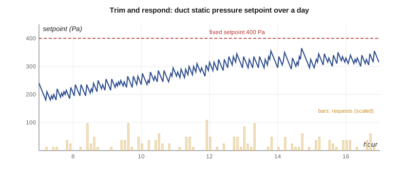
Many of the Guideline 36 resets use a logic called trim and respond. Each zone or terminal that cannot meet its need sends requests: a VAV terminal whose damper is nearly fully open sends a static pressure request, a fan coil whose chilled water valve is nearly fully open sends a chilled water request. The system controller periodically trims its setpoint, lowering the duct static pressure or raising the chilled water temperature by a small step, and, when the number of requests exceeds a number it is told to ignore, it responds by moving the setpoint the other way in proportion to the requests, up to a maximum step. The setpoint therefore drifts down to the lowest value that keeps the most demanding zones satisfied, and rises quickly when they complain.
# Trim and respond reset of the DOAS duct static pressure setpoint, in the style of ASHRAE Guideline 36
import random
random.seed(36)
SPmin, SPmax, SP = 75.0, 400.0, 250.0                # Pa limits and initial setpoint
trim, respond, max_resp, ignores = -10.0, 15.0, 40.0, 2   # Pa per step; requests ignored before responding
zones = 24
def damper_positions(sp, hour):                       # each zone damper opens further when duct pressure is low
    load = 0.55 + 0.35*max(0.0, min(1.0, (hour - 7)/6))  # morning to afternoon demand
    return [min(100.0, (40 + 60*load*random.uniform(0.6, 1.25))*(260/sp)**0.5) for _ in range(zones)]
log = []
for step in range(0, 10*30):                          # 10 hours, a step every 2 minutes
    hour = 7 + step*2/60
    pos = damper_positions(SP, hour)
    requests = sum(1 for p in pos if p > 95) + sum(1 for p in pos if p > 99)   # one request above 95 %, two above 99 %
    R = requests - ignores
    SP = SP + (min(max_resp, R*respond) if R > 0 else trim)
    SP = max(SPmin, min(SPmax, SP))
    if step % 30 == 0: log.append((hour, SP, requests, max(pos)))
print(" time   setpoint (Pa)   requests   most-open damper (%)")
for hour, sp, r, mx in log:
    print(f"{int(hour):02d}:{int(60*(hour % 1)):02d}      {sp:5.0f}         {r:3d}          {mx:5.1f}")
avg = sum(sp for _, sp, _, _ in log)/len(log)
print(f"Average setpoint {avg:.0f} Pa vs fixed 400 Pa: fan power falls roughly in proportion, about {100*(1 - avg/400):.0f} % less static work")
# Chilled water supply temperature reset: warmer water when the fan coils are satisfied (helps the district return)
for oat in (30, 24, 18, 12):
    chw = 7 + (24 - min(24, max(12, oat)))/12*3
print(f"outdoor {oat:2d} C -> chilled water supply setpoint {chw:.1f} C")time setpoint (Pa) requests most-open damper (%) 07:00 240 0 82.5 08:00 205 0 94.1 09:00 245 0 86.9 10:00 235 2 97.2 11:00 275 0 93.0 12:00 315 4 98.0 13:00 335 7 100.0 14:00 295 1 97.2 15:00 315 0 94.9 16:00 330 3 97.6 Average setpoint 279 Pa vs fixed 400 Pa: fan power falls roughly in proportion, about 30 % less static work outdoor 30 C -> chilled water supply setpoint 7.0 C outdoor 24 C -> chilled water supply setpoint 7.0 C outdoor 18 C -> chilled water supply setpoint 8.5 C outdoor 12 C -> chilled water supply setpoint 10.0 C
The program applies trim and respond to the DOAS supply duct, which in the offices and community room serves variable-volume ventilation terminals with occupancy sensors. The setpoint starts at 250 Pa and trims by 10 Pa every two minutes; requests from terminals whose dampers are more than 95 percent open push it up by 15 Pa each, after two are ignored. Over the day the setpoint wanders between about 180 and 365 Pa, averaging about 280 Pa, compared with the 400 Pa a designer might have fixed. Because fan power at a given flow is roughly proportional to the pressure it develops, the saving in static pressure work is about 30 percent. The second part of the program resets the building chilled water supply from 7 °C on hot days to 10 °C on mild ones, which raises the return temperature, helps the cooling exchanger and pleases Riverside General Hospital's utility partner.
The DOAS sequence
The dedicated outdoor air unit's sequence is the heart of the building's controls. In outline:
The unit runs on the occupancy schedule, starting early enough to purge the building before staff arrive, and continuously for the urgent care unit's separate system. The supply fan array holds the duct static pressure setpoint, reset by trim and respond. The outdoor air flow is measured at the intake and the exhaust fan tracks it with a fixed offset so that the building stays slightly positive. In cooling, the cooling coil valve modulates to hold the leaving air dew point at the setpoint from Lesson 2, about 9.9 °C, reset upward when the space humidity sensors show the rooms are dry; the supply air is then reheated by the energy recovery wheel's sensible effect or the heating coil only if the rooms are overcooled, which in practice happens on mild humid days. In heating, the wheel runs at full speed and the heating coil holds a supply temperature of 18 °C, reset between 16 and 20 °C by the zone heating and cooling demands. Below the wheel's frost threshold the wheel speed is reduced and the preheat coil protects it, as Lesson 6 described.
Every sequence includes failure responses. If the supply fan array loses a fan, the remaining fans speed up and an alarm is raised. If the leaving air temperature falls below 4 °C in winter, a freeze protection routine opens the heating valve fully, stops the outdoor air flow if necessary and alarms. If the dew point cannot be held, the zone fan coils are allowed to dehumidify, and their drain pans are monitored for water.
Zone and terminal control
Each room has a sensor for temperature, and the offices, community room and waiting areas also have occupancy and carbon dioxide sensors. A fan coil runs its fan at the lowest speed that meets the load, modulating its cooling or heating valve, with a dead band between heating and cooling setpoints, typically 2 to 3 K wide, in which neither valve opens. The dead band is essential: without it, a room hovering at its setpoint can heat and cool alternately, wasting energy in both. When a room is unoccupied, its setpoints widen and its ventilation terminal closes to a minimum, which is demand-controlled ventilation in its simplest form. The examination rooms have a local button that raises the setpoint to 26 °C for an hour, for gowned patients, and then returns it.
| Control strategy | What it does | Typical saving or benefit |
|---|---|---|
| Duct static pressure reset | lowers fan pressure to what the zones need | 20 to 40 % of fan energy in variable systems |
| Chilled water supply reset | raises chilled water temperature when loads are low | higher return temperature, lower pump and plant energy |
| Heating water supply reset | lowers heating water temperature in mild weather | cooler returns, better heat pump and boiler efficiency |
| Demand-controlled ventilation | reduces outdoor air in unoccupied or lightly used rooms | large ventilation savings in variable-occupancy spaces |
| Optimal start | starts systems just early enough for occupancy | avoids early starts; shorter warm-up |
| Dead bands and interlocks | prevent simultaneous heating and cooling | avoids waste and hunting |
Fault detection and monitoring
Controls drift. Sensors lose calibration, valves stick, dampers fail, and programmers change setpoints in response to complaints and forget to change them back. Guideline 36 includes automated fault detection and diagnostics rules for air handlers: for example, the controller compares the mixed, supply and outdoor air temperatures and flags a fault if the cooling coil valve is closed but the supply air is much colder than the mixed air, which suggests a leaking valve. The health centre's building automation system will log trends of every point at short intervals and keep them for at least a year, so that problems can be seen and fixed. Northgate's own meters at the energy transfer station add a check from outside: if the building's chilled water return temperature falls, the utility will notice before the building does.
Cybersecurity and integration
Building automation systems are now networked computers and must be treated as such. The specifications require the building automation network to be separated from the hospital's clinical and administrative networks, with access through authorized, monitored connections; default passwords to be changed and accounts managed; and software to be kept updated by the controls contractor under the service contract. Open protocols, such as BACnet, allow equipment from different makers to share data, and the energy transfer station's controller, which belongs to Northgate, exchanges a defined list of points with the building system through a secure gateway. Responsibility for each controller, whether the hospital's or Northgate's, is written down.
Worked problem
Dead band and simultaneous operation
A fan coil has a heating setpoint of 21.0 °C and a cooling setpoint of 23.5 °C. The room temperature is 22.4 °C. What should each valve do, and what would happen if both setpoints were 22.0 °C?
Show solution
- 22.4 °C lies within the 2.5 K dead band, so both valves stay closed and the fan runs at minimum or stops.
- With a single setpoint of 22.0 °C, the cooling valve would open at 22.4 °C; the room would cool past 22.0 °C and the heating valve would open; small overshoots in each direction would cycle the valves continually.
Answer: Both valves stay closed. A dead band is cheap insurance against hunting and simultaneous heating and cooling, and Guideline 36 requires one.
Common mistakes
MistakeSpecifying controls with vague performance words.
InsteadWrite specific, testable sequences, using Guideline 36 where it applies.
MistakeFixing duct static pressure and chilled water setpoints at design values.
InsteadReset them with trim and respond from zone requests.
MistakeUsing a single setpoint for heating and cooling.
InsteadProvide a dead band so that heating and cooling cannot fight.
MistakeLeaving fault detection to the operators.
InsteadSpecify automated fault rules and long-term trend storage.
MistakeConnecting the building automation system to the corporate network without protection.
InsteadSeparate it, manage access and keep it updated.
Summary and key terms
- Sequences of operation state exactly how each system runs, resets, alarms and fails.
- ASHRAE Guideline 36, revised in 2024, gives tested sequences that can be specified by reference.
- Trim and respond lowers setpoints until zones ask for more, then responds in proportion to requests.
- In the program the static pressure setpoint averages about 280 Pa instead of 400 Pa.
- The DOAS controls dew point in cooling and supply temperature in heating, with frost and freeze protection.
- Dead bands, fault detection, trend logs and network security protect performance over time.
- Sequence of operations
- A written description of how a system is to be controlled in all modes and conditions.
- Trim and respond
- A reset method that steps a setpoint toward saving energy and back in response to requests from zones.
- Request
- A signal from a zone or terminal that it cannot meet its need at the current setpoint.
- Dead band
- A range of temperature between heating and cooling setpoints in which neither operates.
- Optimal start
- Starting HVAC equipment at the latest time that still achieves comfort by occupancy.
- Fault detection and diagnostics
- Automated analysis of system data to identify and explain faults.
- Building automation system
- The networked control system that monitors and operates building equipment.
- BACnet
- An open data communication protocol for building automation and control networks.
Practice problems
Work each problem on paper first, then reveal the answer to check.
A trim-and-respond loop trims 10 Pa per step and responds 15 Pa per request after ignoring 2. With 5 requests, how does the setpoint change?
Show answer
Up by \(3 \times 15 = 45\) Pa, limited to the maximum response, 40 Pa in the program.
Why does a reset of duct static pressure from 400 to 280 Pa save fan energy at the same flow?
Show answer
Fan power is proportional to flow times the pressure it develops.
State one failure response for the DOAS in winter.
Show answer
Freeze protection: if leaving air falls below 4 °C, open the heating valve fully and alarm.
In the program, what happens to the average setpoint if the number of ignored requests is raised to 4?
Show answer
It falls further, because more zones must complain before the controller responds.
Why are the examination rooms given a timed setpoint button?
Show answer
To warm the room for a gowned patient and return to normal automatically.
Lesson quiz · 5 questions
Score 60% or more to complete this lesson.
Create a free account to save your progress, take quizzes and earn a certificate.