
MEC-395 · Lesson 8 of 12 · 22 min
Pressure measurement
Pump head is the quantity a pump exists to produce, and on TL-3 it comes from two pressure transducers, a barometer and a tape measure. Lesson 3 showed that the transducers contribute about 14 percent of the variance of efficiency, which is modest. But head is also the quantity most easily spoiled by installation mistakes that no uncertainty budget would reveal: a bubble of air in an impulse line, a forgotten velocity term, a gauge height measured to the wrong point. This lesson covers how pressure is measured, how pressure instruments are calibrated, and how the head calculation is done properly.
Pressure references and units
Pressure is force per unit area, in pascals, though engineers commonly use kilopascals, bars (100 kPa) and, particularly in the United States, pounds per square inch. Pressure is always measured against a reference. Absolute pressure is measured from a perfect vacuum. Gauge pressure is measured from the local atmospheric pressure, so it changes with the weather even when the absolute pressure does not. Differential pressure is the difference between two points in a system. A sealed-gauge transducer measures against a fixed pressure trapped inside it, approximately atmospheric when it was sealed. Confusing these references is one of the commonest and largest mistakes in pressure measurement, as the program in this lesson shows.
In Canadian practice pressures are normally stated in kilopascals or bars, and gauge readings are often marked kPa(g) or bar(g) to make the reference explicit. Pump head itself is a length, in metres of the liquid being pumped.
Liquid columns and manometers
The oldest pressure instrument is the manometer, a tube of liquid whose height difference h balances the pressure difference, \(\Delta p = \rho g h\). A manometer is a primary instrument in the sense that, given the liquid's density and local gravity, it needs no calibration. U-tube, well-type and inclined manometers are still used for low pressure differences, and water manometers remain a good way to check differential transducers on low-pressure ventilation and fan tests. Their limitations are practical: they are slow, they need careful reading, they are fragile, and their liquids must be clean and at a known temperature.
The same physics sets a trap in every liquid pressure measurement: the transducer measures the pressure at its own diaphragm, not at the pipe tapping. If the transducer is above or below the tapping and the line between them is full of water, the reading differs from the tapping pressure by \(\rho g \Delta z\), about 0.098 bar per metre of water. That is why the head calculation uses the heights of the transducers themselves, and why the lines must be completely full of water, with no trapped air, for the correction to be valid.
Mechanical and electronic pressure sensors
The Bourdon tube, a curved, flattened tube that straightens under internal pressure and moves a pointer through a linkage, is the familiar dial gauge. Test-grade Bourdon gauges with large dials can be accurate to 0.25 percent of span, but they suffer from friction, hysteresis and the operator's reading of the pointer, and they cannot be logged. Bellows and diaphragm gauges work on the same principle for lower pressures.
Electronic transducers measure the deflection or strain of a diaphragm. In piezoresistive transducers, the type used for PT-110 and PT-210, the diaphragm is a thin silicon membrane with strain-sensitive resistors diffused into its surface, wired as a bridge; silicon's piezoresistive effect gives a gauge factor around a hundred times larger than metal foil. Capacitive transducers measure the change in capacitance between the diaphragm and a fixed plate and are noted for stability and overpressure tolerance. Resonant transducers measure the change in natural frequency of a vibrating element under stress, and the best of them are accurate to a few thousandths of a percent of span, which makes them suitable as working standards. Piezoelectric transducers generate charge when stressed; they cannot measure steady pressure because the charge leaks away, but they excel at fast dynamic pressures such as pulsation and combustion.
| Sensor type | Principle | Strengths | Limitations |
|---|---|---|---|
| Manometer | Liquid column height | Primary, simple, cheap | Slow, fragile, low pressures only |
| Bourdon gauge | Curved tube straightens | No power, robust | Friction, hysteresis, cannot be logged |
| Piezoresistive | Diffused silicon strain resistors | Small, fast, accurate, inexpensive | Temperature effects need compensation |
| Capacitive | Diaphragm-to-plate capacitance | Stable, overpressure tolerant | More complex electronics |
| Resonant | Frequency of a stressed resonator | Very high accuracy and stability | Cost |
| Piezoelectric | Charge from stressed crystal | Very fast, wide dynamic range | No steady (static) pressure |
Calibration: the deadweight tester
The deadweight tester, or pressure balance, is the standard against which Tidewater's transducers are calibrated. A vertical piston of precisely known effective area A fits in a cylinder with a very small clearance; masses m are loaded on the piston and it is spun gently to eliminate friction; the oil pressure under the piston rises until it floats, and then \(p = mg/A\). The instrument's accuracy depends on knowing the masses, the piston area and local gravity.
Gravity is the term most often forgotten. The masses of a deadweight tester are often marked with the pressure they generate at standard gravity, 9.80665 m/s², but local gravity varies with latitude and elevation by about half a percent over the Earth's surface. The certificate of a pressure balance states the conditions its values refer to, and the user applies corrections for local gravity and, where the certificate's values do not already include it, for the buoyancy of the masses in air. The program works out local gravity in Moncton from a standard formula for the Earth's normal gravity field, which is adequate for this purpose; laboratories that need better use a measured value for their site.
# Pressure measurement for pump head: local gravity, the deadweight tester and the total head calculation
import math
lat, h_site = 46.09, 20                   # site latitude (deg) and elevation (m)
phi = math.radians(lat)
g = 9.780327*(1 + 0.0053024*math.sin(phi)**2 - 0.0000058*math.sin(2*phi)**2) - 3.086e-6*h_site
g0 = 9.80665
print(f"Local gravity in Moncton: {g:.5f} m/s2 (standard gravity {g0} m/s2, ratio {g/g0:.6f})")
# Deadweight tester: masses marked for nominal pressure at standard gravity, piston area 1.0 cm2 (approx.)
nominal = 3.0                                  # bar marked on the mass stack
rho_air, rho_mass = 1.2, 7900.0                # air buoyancy on stainless steel masses
p_true = nominal*(g/g0)*(1 - rho_air/rho_mass)
print(f"Mass stack marked {nominal:.1f} bar actually generates {p_true:.5f} bar here: correction {1e3*(p_true - nominal):+.2f} mbar ({100*(p_true/nominal - 1):+.4f} %)")
print(f"  of which gravity {100*(g/g0 - 1):+.4f} % and air buoyancy {100*(-rho_air/rho_mass):+.4f} %")
# Total head of the TP-80 at the guarantee point
rho = 998.2                                    # water at 20 C, kg/m3
Q = 90.08/3600
pd_g, ps_abs, pb = 3.240e5, 1.130e5, 1.013e5   # Pa: discharge gauge, suction absolute, barometer
zd, zs = 0.450, 0.250                          # m above the pump datum (shaft centreline) of the transducer diaphragms
Ds, Dd = 0.125, 0.100                          # pipe inside diameters at the tappings
v1, v2 = Q/(math.pi*Ds**2/4), Q/(math.pi*Dd**2/4)
pressure_term = ((pd_g + pb) - ps_abs)/(rho*g)
elev_term = zd - zs
vel_term = (v2**2 - v1**2)/(2*g)
H = pressure_term + elev_term + vel_term
print(f"\nVelocities: suction {v1:.2f} m/s, discharge {v2:.2f} m/s")
print(f"Head = pressure {pressure_term:.3f} m + elevation {elev_term:.3f} m + velocity {vel_term:.3f} m = {H:.3f} m")
print("Errors if a term is mishandled:")
print(f"  velocity heads left out:          {-vel_term:+.3f} m ({-100*vel_term/H:+.2f} %)")
print(f"  gauge heights left out:           {-elev_term:+.3f} m ({-100*elev_term/H:+.2f} %)")
print(f"  suction treated as gauge reading: {-pb/(rho*g):+.3f} m ({-100*pb/(rho*g)/H:+.1f} %)")
print(f"  air bubble in the discharge line holding 0.10 m of water out: {-0.10:+.3f} m ({-100*0.10/H:+.2f} %)")
# The same head expressed in pressure units, for comparison with the US convention
print(f"\nPressure rise {((pd_g + pb) - ps_abs)/1e5:.3f} bar = {((pd_g + pb) - ps_abs)/6894.76:.2f} psi; head {H:.2f} m = {H/0.3048:.1f} ft")Local gravity in Moncton: 9.80712 m/s2 (standard gravity 9.80665 m/s2, ratio 1.000048) Mass stack marked 3.0 bar actually generates 2.99969 bar here: correction -0.31 mbar (-0.0104 %) of which gravity +0.0048 % and air buoyancy -0.0152 % Velocities: suction 2.04 m/s, discharge 3.19 m/s Head = pressure 31.902 m + elevation 0.200 m + velocity 0.306 m = 32.407 m Errors if a term is mishandled: velocity heads left out: -0.306 m (-0.94 %) gauge heights left out: -0.200 m (-0.62 %) suction treated as gauge reading: -10.348 m (-31.9 %) air bubble in the discharge line holding 0.10 m of water out: -0.100 m (-0.31 %) Pressure rise 3.123 bar = 45.30 psi; head 32.41 m = 106.3 ft
In Moncton, local gravity is 9.80712 m/s², slightly above standard, so the gravity correction is +0.005 percent. The buoyancy correction of −0.015 percent, if it applies, is larger. Together they change a nominal 3.000 bar by −0.31 mbar, about a tenth of PT-210's tolerance. The corrections are small here, but they are systematic, they apply to every calibration, and at other sites they are much larger: a balance used without correction near the equator or at high altitude could be in error by a few tenths of a percent.
Pressure tappings and impulse lines
A pressure tapping is a hole drilled through the pipe wall, and its quality matters more than its appearance suggests. The hole should be small, typically a few millimetres, drilled perpendicular to the wall, and free of burrs, because a burr projecting into the flow creates a local stagnation or suction that shifts the reading. The pipe must be straight and free of fittings for some distance upstream so the flow is not swirling or distorted. ANSI/HI 14.6 and ISO 9906 specify where the measuring sections for a pump test should be, close to the pump flanges, typically at about two pipe diameters from them, and how many tappings to use; for higher grades of test, several tappings around the circumference are connected by a ring manifold so that the reading averages out any nonuniformity.
Impulse lines, the tubes connecting tappings to transducers, must be completely full of the measured liquid. Lines should slope continuously upward from the tapping to a vent at the transducer, or downward to it, so that air rises out of them, and they must be vented at the start of each test. An air bubble trapped in a line breaks the water column; if 0.10 m of the line's height is occupied by air instead of water, the reading is low by about 0.01 bar, which is a 0.3 percent error in head, larger than the transducer's whole uncertainty. Gilles vents every line before every test and checks the zero of each transducer with the pump stopped and the loop static, when both should read the same static head corrected for their heights.
Calculating pump total head
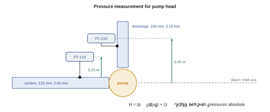
Total head is the increase in the total energy of the liquid between the pump's inlet and outlet, expressed as a height of liquid. With pressures in consistent units, the heights z of the transducers above the pump's datum, and the mean velocities v at the measuring sections, it is
The datum for a horizontal pump is the shaft centreline, though for head itself only height differences matter. On TL-3 the suction transducer PT-110 reads absolute pressure because Tidewater also runs suction tests, in which the suction pressure is lowered until the pump cavitates, and those need absolute pressure directly; the discharge transducer PT-210 reads gauge pressure, so the barometer reading is added to it. The two references must not be mixed: treating the absolute suction reading as if it were gauge would put an error of a whole atmosphere, about 10.3 m of water, into the head.
At the guarantee point the pressure term is 31.90 m, the elevation term 0.20 m and the velocity term 0.31 m, giving 32.41 m. The velocity term arises because the discharge pipe is smaller than the suction pipe, so the water leaves faster than it arrived. Leaving it out would understate head by nearly one percent, and leaving out the elevation term by six tenths of a percent, either of which would exceed the whole measurement uncertainty of Lesson 3. These are not refinements; they are part of the definition of the measurand.
Worked problem
Zero check with the pump stopped
With the loop full and the pump stopped, PT-110 reads 1.1282 bar absolute and PT-210 reads 0.1131 bar gauge, while the barometer reads 1.0130 bar. The transducers are 0.25 m and 0.45 m above the datum, water density is 998.2 kg/m³ and g = 9.807 m/s². Do the readings agree?
Show solution
- With no flow, the absolute pressure at the higher transducer should be lower by \(\rho g \Delta z = 998.2 \times 9.807 \times 0.20 = 1958\) Pa = 0.0196 bar.
- PT-210 in absolute terms: \(0.1131 + 1.0130 = 1.1261\) bar.
- Expected: \(1.1282 - 0.0196 = 1.1086\) bar. The difference is \(1.1261 - 1.1086 = 0.0175\) bar.
Answer: The readings disagree by 17.5 mbar, far more than the transducers' tolerances. The likely cause is air in one of the impulse lines, or a wrong height; Gilles vents both lines and repeats the check before any test is run.
The example shows why the static zero check is part of the test procedure. With the lines properly vented, the two transducers agree within a few millibars, and the test can begin.
Common mistakes
MistakeMixing absolute and gauge readings in the head calculation.
InsteadConvert both to the same reference using the barometer.
MistakeUsing the heights of the pipe tappings instead of the transducers.
InsteadWith water-filled lines, use the heights of the transducer diaphragms.
MistakeLeaving out the velocity head when pipe sizes differ.
InsteadInclude it; on the TP-80 it is nearly one percent of head.
MistakeCalibrating with a deadweight tester at standard gravity.
InsteadApply local gravity and any buoyancy correction stated on the certificate.
MistakeStarting a test without venting impulse lines.
InsteadVent every line and check the static zero before testing.
Summary and key terms
- Pressure is absolute, gauge, differential or sealed gauge; references must not be mixed.
- A water-filled line adds ρgΔz between tapping and transducer, about 0.098 bar per metre.
- Piezoresistive transducers measure diaphragm strain with silicon resistors; piezoelectric sensors measure only changing pressure.
- Deadweight testers give p = mg/A; local gravity and buoyancy corrections are systematic and must be applied.
- Total head includes pressure, elevation and velocity terms: 31.90 + 0.20 + 0.31 = 32.41 m for the TP-80.
- Tappings must be clean and well placed; impulse lines must be vented, and a static zero check catches trapped air.
- Absolute pressure
- Pressure measured from a perfect vacuum.
- Gauge pressure
- Pressure measured relative to the local atmospheric pressure.
- Differential pressure
- The difference in pressure between two points.
- Manometer
- An instrument that measures pressure by the height of a liquid column.
- Bourdon tube
- A curved tube that straightens under pressure, used in dial gauges.
- Piezoresistive transducer
- A pressure sensor using strain-sensitive resistors in a silicon diaphragm.
- Deadweight tester
- A primary pressure standard in which known masses on a piston of known area generate a known pressure.
- Pressure tapping
- A hole in a pipe wall through which static pressure is measured.
- Impulse line
- The tube connecting a pressure tapping to a pressure instrument.
- Total head
- The increase in total energy of the liquid across the pump, expressed as a height of liquid.
Practice problems
Work each problem on paper first, then reveal the answer to check.
A transducer reads 2.50 bar gauge with the barometer at 0.99 bar. What is the absolute pressure?
Show answer
3.49 bar.
A transducer is 1.5 m below its tapping with a water-filled line. How much does its reading exceed the tapping pressure?
Show answer
998 × 9.81 × 1.5 = 14.7 kPa, or 0.147 bar.
In the program, what is the velocity head if the discharge pipe were also 125 mm?
Show answer
Zero; equal pipe sizes give equal velocities.
A deadweight tester is used where g = 9.7950 m/s² without correction. What is the gravity error?
Show answer
9.7950/9.80665 − 1 = −0.12 percent.
Why can a piezoelectric transducer not be used to measure PT-210's steady discharge pressure?
Show answer
Its charge leaks away, so it responds only to changing pressure.
Lesson quiz · 5 questions
Score 60% or more to complete this lesson.
Create a free account to save your progress, take quizzes and earn a certificate.