
MEC-360 · Lesson 9 of 12 · 23 min
Gear tooth strength: bending and contact stress
With the GR-5's geometry and forces known, Owen must show that the teeth will survive. Gear teeth fail in two main ways. A tooth can break off at the root, a bending fatigue failure that is sudden and usually ends the gearbox's service at once. Or the tooth faces can develop pits, a surface fatigue failure caused by the repeated contact stress, which grows slowly, makes the gears noisy and eventually destroys the profile. Both failures must be checked, and for through-hardened industrial gears like the GR-5, it is usually the surface that governs. This lesson starts with the classical Lewis equation for bending, then outlines the AGMA approach used in practice for both bending and contact.
Tooth bending: the Lewis equation
In 1892 Wilfred Lewis proposed treating a gear tooth as a cantilever beam loaded at its tip by the tangential force. The weakest section is where a parabola of uniform strength, inscribed in the tooth profile, touches the root fillets. The result is the Lewis equation:
where F is the face width, m the module and Y the Lewis form factor, a dimensionless number that depends on the tooth shape and therefore on the number of teeth and the pressure angle. Y increases with the number of teeth, because teeth on larger gears have wider bases. For 20° full-depth teeth, Y is about 0.30 at 16 teeth, 0.309 at 18 teeth, 0.34 at 24 teeth, 0.36 at 30 teeth and about 0.43 at 76 teeth, approaching 0.485 for a rack. Note that in US units with diametral pitch the equation is written \(\sigma = W_t P_d/(F Y)\).
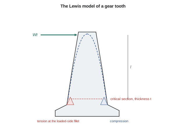
Lewis's equation assumes the whole load acts at the tip of one tooth, ignores the radial component of the force, and ignores the stress concentration at the root fillet and the dynamic effects of tooth errors. It was extended early on with a velocity factor \(K_v\), an empirical allowance for the dynamic load caused by tooth spacing and profile errors, which grows with pitch-line velocity. Carl Barth's factor for cut or milled teeth is \(K_v = (6.1 + V)/6.1\) with V in m/s; for hobbed or shaped teeth \((3.56 + \sqrt V)/3.56\) is used. The Lewis equation with a velocity factor is still a useful first estimate.
Worked problem
Lewis bending stress on the GR-5 pinion
The GR-5 pinion has 18 teeth, m = 3 mm, F = 36 mm, and carries \(W_t = 1507\) N at V = 4.98 m/s. Estimate the bending stress with the Barth factor for cut teeth.
Show solution
- \[K_v = \frac{6.1 + 4.98}{6.1} = 1.82\]
- \[\sigma = \frac{K_v W_t}{F m Y} = \frac{1.82 \times 1507}{36 \times 3 \times 0.309} = 82\ \text{MPa}\]
Answer: A stress of 82 MPa is low for a quenched and tempered alloy steel. The Lewis estimate does not include stress concentration or load sharing, so it is a check on order of magnitude rather than a final rating.
The AGMA approach
The American Gear Manufacturers Association's rating standard, ANSI/AGMA 2001-D04 (reaffirmed since its publication), and the international ISO 6336 series rate gears for both bending and pitting resistance using a modified Lewis form for bending and a Hertzian form for contact, each multiplied by factors for the conditions of service. In SI form, the AGMA bending stress equation is
and the contact (pitting) stress equation is
| Factor | Meaning | GR-5 value (approximate) |
|---|---|---|
| \(K_o\) | Overload: shock from driver and driven machine | 1.25 (electric motor, moderate shock) |
| \(K_v\) | Dynamic: tooth errors and speed | 1.26 (quality level Q_v = 8) |
| \(K_s\) | Size: large teeth weaker per unit area | 1.0 |
| \(K_H\) (also \(K_m\)) | Load distribution across the face | 1.22 (open to enclosed gearing, moderate face width) |
| \(K_B\) | Rim thickness | 1.0 (solid gear blank) |
| \(Y_J\) (also J) | Bending geometry factor, includes root stress concentration and load sharing | 0.32 pinion, 0.41 gear |
| \(Z_E\) | Elastic coefficient | 191 \(\sqrt{\text{MPa}}\) for steel on steel |
| \(Z_I\) (also I) | Pitting geometry factor | \(\dfrac{\cos\phi\sin\phi}{2}\dfrac{m_G}{m_G + 1}\) = 0.130 for external spur gears |
| \(Z_R\) | Surface condition | 1.0 |
The dynamic factor in the current AGMA method depends on a transmission accuracy level \(Q_v\) and the pitch-line velocity: \(K_v = \big((A + \sqrt{200V})/A\big)^B\) with \(B = 0.25(12 - Q_v)^{2/3}\) and \(A = 50 + 56(1 - B)\), V in m/s. For quality level 8 at 4.98 m/s it gives 1.26, much smaller than Barth's cut-tooth factor, because modern hobbed and finished gears are far more accurate than the cut gears of Barth's day.
Allowable stresses and safety factors
The calculated stresses are compared with allowable stress numbers for the material, which depend on hardness and heat treatment and are adjusted for life, temperature and reliability:
For through-hardened steel of grade 1 quality, AGMA gives allowable bending and contact stress numbers that rise with Brinell hardness, approximately \(\sigma_{FP} = 0.533\,HB + 88.3\) MPa and \(\sigma_{HP} = 2.22\,HB + 200\) MPa. These values are for 10⁷ cycles at 99 percent reliability; the stress cycle factors \(Y_N\) and \(Z_N\) adjust them for other lives, falling slowly below one for lives beyond 10⁷ cycles. Case-carburized gears have much higher allowables, roughly 1,240 MPa or more in contact, which is why heavily loaded industrial and automotive gears are carburized and ground.
Because contact stress is proportional to the square root of the load, the bending factor \(S_F\) and the contact factor \(S_H\) are not directly comparable. To compare them on a load basis, \(S_F\) is compared with \(S_H^{\,2}\); whichever is smaller indicates the governing failure mode.
# GR-5 spur stage: Lewis bending stress, then an AGMA-style bending and contact check
import math
m, F, Np, Ng = 3.0, 36.0, 18, 76               # mm, mm
phi = math.radians(20); Wt = 1507.0; V = 4.98   # N, m/s (from Lesson 8)
dp = m * Np; mG = Ng / Np
# Lewis with the Barth velocity factor for cut or milled teeth
Y = 0.309                                      # Lewis form factor, 18 teeth, full depth
Kv_barth = (6.1 + V) / 6.1
s_lewis = Kv_barth * Wt / (F * m * Y)
print(f"Lewis: Kv = {Kv_barth:.2f}, bending stress = {s_lewis:.0f} MPa")

# AGMA-style factors (approximate values for this example)
Qv = 8
B = 0.25 * (12 - Qv) ** (2 / 3); A = 50 + 56 * (1 - B)
Kv = ((A + math.sqrt(200 * V)) / A) ** B
Ko, Ks, Km, KB = 1.25, 1.0, 1.22, 1.0           # overload (electric motor, moderate shock), size, load distribution, rim
J_p, J_g = 0.32, 0.41                          # bending geometry factors (approximate)
sb_p = Wt * Ko * Kv * Ks * Km * KB / (F * m * J_p)
sb_g = Wt * Ko * Kv * Ks * Km * KB / (F * m * J_g)
ZE = 191.0                                     # elastic coefficient, steel on steel, sqrt(MPa)
I = math.cos(phi) * math.sin(phi) / 2 * mG / (mG + 1)
sc = ZE * math.sqrt(Wt * Ko * Kv * Ks * Km / (dp * F * I))
print(f"AGMA-style: Kv = {Kv:.3f}, I = {I:.3f}")
print(f"bending stress pinion {sb_p:.0f} MPa, gear {sb_g:.0f} MPa; contact stress {sc:.0f} MPa")

# Allowable stresses for through-hardened grade 1 steel and life factors
HBp, HBg = 300, 260
St = lambda HB: 0.533 * HB + 88.3              # MPa, bending
Sc = lambda HB: 2.22 * HB + 200                # MPa, contact
hours = 20000
Np_cycles = 1760 * 60 * hours; Ng_cycles = Np_cycles / mG
YN = lambda N: 1.3558 * N ** -0.0178
ZN = lambda N: 1.4488 * N ** -0.023
KR = 1.0                                       # 99 % reliability
SF_p = St(HBp) * YN(Np_cycles) / KR / sb_p
SF_g = St(HBg) * YN(Ng_cycles) / KR / sb_g
SH_p = Sc(HBp) * ZN(Np_cycles) / KR / sc
SH_g = Sc(HBg) * ZN(Ng_cycles) / KR / sc
print(f"pinion cycles {Np_cycles:.2e}: YN = {YN(Np_cycles):.3f}, ZN = {ZN(Np_cycles):.3f}")
print(f"bending safety factors: pinion {SF_p:.2f}, gear {SF_g:.2f}")
print(f"contact safety factors: pinion {SH_p:.2f}, gear {SH_g:.2f}  (compare SF with SH squared: {SH_p**2:.2f}, {SH_g**2:.2f})")

# Contact governs. Options: a harder gear, a wider face, or both
for Fw, HBg2 in ((36, 300), (45, 260), (45, 300)):
    sc2 = ZE * math.sqrt(Wt * Ko * Kv * Ks * Km / (dp * Fw * I))
print(f"face {Fw} mm, gear {HBg2} HB: contact stress {sc2:.0f} MPa, gear SH = {Sc(HBg2)*ZN(Ng_cycles)/sc2:.2f}, pinion SH = {Sc(HBp)*ZN(Np_cycles)/sc2:.2f}")Lewis: Kv = 1.82, bending stress = 82 MPa AGMA-style: Kv = 1.262, I = 0.130 bending stress pinion 84 MPa, gear 65 MPa; contact stress 647 MPa pinion cycles 2.11e+09: YN = 0.925, ZN = 0.884 bending safety factors: pinion 2.74, gear 3.29 contact safety factors: pinion 1.18, gear 1.10 (compare SF with SH squared: 1.40, 1.20) face 36 mm, gear 300 HB: contact stress 647 MPa, gear SH = 1.22, pinion SH = 1.18 face 45 mm, gear 260 HB: contact stress 579 MPa, gear SH = 1.23, pinion SH = 1.32 face 45 mm, gear 300 HB: contact stress 579 MPa, gear SH = 1.37, pinion SH = 1.32
Worked problem
Pitting resistance of the GR-5
The GR-5 pinion is 300 HB and the gear 260 HB. For 20,000 hours of service find the contact safety factors.
Show solution
- \[\sigma_c = 191\sqrt{\frac{1507 \times 1.25 \times 1.262 \times 1.22}{54 \times 36 \times 0.130}} = 647\ \text{MPa}\]
- Pinion cycles \(1760 \times 60 \times 20\,000 = 2.11 \times 10^9\), so \(Z_N = 0.884\); gear cycles \(5.0 \times 10^8\), so \(Z_N = 0.91\).
- Pinion: \(\sigma_{HP} = 2.22(300) + 200 = 866\) MPa; \(S_H = 866 \times 0.884/647 = 1.18\).
- Gear: \(\sigma_{HP} = 2.22(260) + 200 = 777\) MPa; \(S_H = 777 \times 0.91/647 = 1.10\).
Answer: Bending is safe, with factors of 2.7 on the pinion and 3.3 on the gear, and \(S_H^2\) of 1.40 and 1.20 confirms that pitting governs. A contact factor of 1.1 on the gear is too low for Tidewater's practice of at least 1.2. The program tries three fixes: raising the gear to 300 HB gives 1.22; widening the face to 45 mm gives 1.23 with the original gear; and both together give 1.37. Owen recommends a 45 mm face with both gears at 300 HB. A wider face needs care, because load distribution across the face worsens with face width and shaft deflection, so the load distribution factor must be rechecked.
Other gear failure modes
Bending fatigue and pitting are the failures the rating standards address directly, but they are not the only ones. Scuffing (also called scoring) is a sudden welding and tearing of the tooth surfaces when the oil film breaks down under high sliding speed and load; it is controlled by lubricant viscosity and additives and by limiting the flash temperature. Wear by abrasion comes from contaminated oil. Micropitting, a fine frosting of the surface, occurs in hardened gears with thin oil films. Tooth breakage from a single overload, such as a jammed sludge pump, is a static failure and is checked against the material's strength with the peak torque. AGMA and ISO publish separate methods for scuffing and micropitting.
Lubrication is part of the gear design. Gear oils are chosen by viscosity for the pitch-line velocity and load, with extreme-pressure additives for heavily loaded gears. For the GR-5, an ISO VG 220 industrial gear oil in a splash bath suits the speed and the moderate temperatures of a pump room.
In Canada, gear rating is commonly done to ISO 6336, the basis of most European gearbox catalogues, or to AGMA 2001, which many North American makers use. The two methods give similar but not identical results, and a gearbox's nameplate rating should state which was used. CSA does not publish a separate gear rating standard.
Common mistakes
MistakeChecking only tooth bending.
InsteadCheck pitting resistance too; for through-hardened gears it often governs.
MistakeComparing S_F directly with S_H.
InsteadCompare S_F with S_H² because contact stress varies with the square root of load.
MistakeUsing Barth's cut-tooth velocity factor for modern hobbed or ground gears.
InsteadUse the AGMA dynamic factor for the gear's accuracy level.
MistakeWidening the face without rechecking load distribution.
InsteadWider faces are more sensitive to misalignment and shaft deflection.
MistakeUsing allowable stresses for 10⁷ cycles for a much longer life.
InsteadApply the stress cycle factors Y_N and Z_N.
Summary and key terms
- Gear teeth fail mainly by root bending fatigue and by surface pitting; both must be checked.
- The Lewis equation σ = W_t/(FmY) treats a tooth as a cantilever; a velocity factor accounts for dynamic load.
- AGMA and ISO methods multiply the basic stresses by factors for overload, dynamics, size, load distribution and rim thickness.
- Contact stress σ_c = Z_E√(W_t…/(d_P F Z_I)) is compared with allowables that rise with hardness.
- For the GR-5, bending factors are 2.7 and 3.3 but the gear's contact factor is only 1.10; a 45 mm face and 300 HB gears raise it to 1.37.
- Scuffing, wear and micropitting are controlled mainly by lubrication.
- Lewis form factor
- A dimensionless factor for tooth shape in the Lewis bending equation.
- Velocity factor
- A factor for the dynamic tooth load caused by tooth errors and speed.
- Pitting
- Surface fatigue of gear teeth, producing small craters in the tooth faces.
- Geometry factor
- A factor for tooth shape, stress concentration and load sharing in the AGMA equations.
- Elastic coefficient
- A factor in the contact stress equation for the elastic properties of the two gear materials.
- Stress cycle factor
- A factor adjusting allowable stresses for the number of load cycles.
- Load distribution factor
- A factor for uneven load across the face width.
- Scuffing
- Adhesive damage of tooth surfaces when the oil film breaks down.
- Case carburizing
- A heat treatment that hardens the tooth surface layer for high contact strength.
Practice problems
Work each problem on paper first, then reveal the answer to check.
A 20-tooth pinion (Y = 0.32) of module 2.5 mm and face 30 mm carries W_t = 1,200 N. Find the Lewis stress without a velocity factor.
Show answer
50 MPa.
Find the Barth factor for cut teeth at V = 8 m/s.
Show answer
2.31.
Find Z_I for a 20° spur pair with m_G = 3.
Show answer
0.121.
Find the AGMA allowable contact stress number for 350 HB steel.
Show answer
About 977 MPa.
In the program, raise the quality level to Q_v = 10. What happens to the gear contact factor?
Show answer
K_v drops to about 1.14 and S_H rises to about 1.16.
Why is pitting more likely than bending to govern a through-hardened gear?
Show answer
Contact allowables rise only moderately with hardness while bending stresses are already low; contact stress is very high at the small contact area.
Lesson quiz · 5 questions
Score 60% or more to complete this lesson.
Create a free account to save your progress, take quizzes and earn a certificate.