
MEC-360 · Lesson 8 of 12 · 21 min
Spur gears: geometry, kinematics and forces
Halfway through the term, Farah moves Owen to the second project. A wastewater utility needs a progressive cavity pump to move thickened sludge, and the PC-150 pump runs at only a few hundred rpm. Tidewater will drive it with a standard four-pole motor through a small reducer of its own design, the GR-5. The first version is a single spur gear stage: an 18-tooth pinion on the motor shaft driving a 76-tooth gear, transmitting 7.5 kW (10 hp) from 1,760 rpm down to about 417 rpm. Spur gears are the simplest gears, with straight teeth parallel to the shaft axis, and they introduce all the ideas needed for the more complex types in Lesson 10. This lesson covers their geometry, how they mesh, and the forces they put on the shafts and bearings.
The law of gearing and the involute
Two gears transmit motion by teeth pushing on each other. For the speed ratio to stay exactly constant as the teeth roll through mesh, the tooth profiles must satisfy the fundamental law of gearing: the common normal to the profiles at the point of contact must always pass through a fixed point on the line of centres, the pitch point. Profiles that satisfy this are called conjugate. Almost all modern gears use the involute of a circle, the curve traced by the end of a taut string unwound from a cylinder, called the base circle. Involute gears have two great advantages: the line of action, along which the contact force acts, is a fixed straight line tangent to both base circles, so the force direction is constant; and the speed ratio stays exact even if the distance between shafts changes slightly, which makes involute gears tolerant of manufacturing and assembly errors.
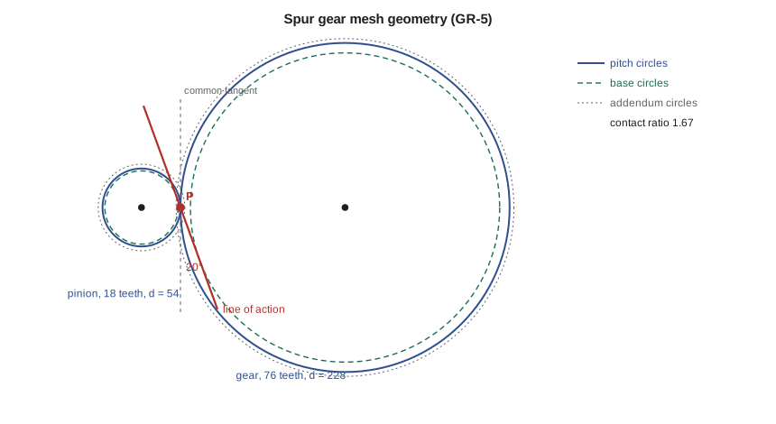
Gear terminology
The pitch circle is the imaginary circle that rolls without slipping on the pitch circle of the mating gear; its diameter is the pitch diameter d. The tooth size is set by the module m in SI practice, the pitch diameter divided by the number of teeth: \(m = d/N\), in millimetres. US practice uses the diametral pitch \(P_d = N/d\) in teeth per inch, the reciprocal idea, with \(m = 25.4/P_d\). The circular pitch \(p = \pi m\) is the distance between corresponding points on adjacent teeth measured along the pitch circle. Standard full-depth teeth have an addendum (height above the pitch circle) of 1 m and a dedendum (depth below it) of 1.25 m, which leaves a clearance of 0.25 m at the root.
| Quantity | Symbol | SI relation | GR-5 pinion / gear |
|---|---|---|---|
| Module | m | — | 3 mm |
| Number of teeth | N | — | 18 / 76 |
| Pitch diameter | d | \(mN\) | 54 / 228 mm |
| Circular pitch | p | \(\pi m\) | 9.42 mm |
| Addendum, dedendum | a, b | \(1.00m,\ 1.25m\) | 3.00, 3.75 mm |
| Outside diameter | \(d_a\) | \(d + 2a\) | 60 / 234 mm |
| Base circle diameter | \(d_b\) | \(d\cos\phi\) | 50.7 / 214.3 mm |
| Distance between centres | C | \((d_P + d_G)/2\) | 141 mm |
| Face width | F | typically 9m to 14m | 36 mm |
The pressure angle \(\phi\) is the angle between the line of action and the common tangent to the pitch circles. The standard is 20°; 14.5° is found on older gears and 25° on some heavily loaded gears. Larger pressure angles give stronger, broader-based teeth and allow fewer pinion teeth without interference, but they increase the radial load on the bearings. Modules and diametral pitches are standardized in preferred series, and cutting tools are made for them, so a designer chooses from standard values: 1, 1.25, 1.5, 2, 2.5, 3, 4, 5, 6 and 8 mm are the first-choice modules.
Kinematics and gear trains
Since the pitch circles roll without slipping, their surface speeds are equal, which gives the speed ratio:
where \(m_G\) is the gear ratio (not to be confused with the module). For the GR-5, \(m_G = 76/18 = 4.222\), so the output turns at 1,760/4.222 = 417 rpm. Choosing tooth numbers that share no common factor spreads wear more evenly; 18 and 76 share a factor of 2, so each pinion tooth only ever meets half of the gear's teeth, and; designers often choose a hunting tooth combination such as 18 and 77 when the exact ratio permits, so that every pinion tooth eventually meets every gear tooth.
The pitch-line velocity, the speed of the pitch circle, is \(V = \pi d_P n_P\). For the GR-5 pinion, \(V = \pi \times 0.054 \times 1760/60 = 4.98\) m/s. Pitch-line velocity affects dynamic loads, noise and the lubrication method: below about 5 m/s, splash lubrication from an oil bath is simple and effective; above about 15 m/s, spray lubrication becomes necessary.
Contact ratio and interference
For smooth motion, a new pair of teeth must come into contact before the previous pair leaves. The contact ratio \(m_c\) is the average number of tooth pairs in contact, found as the length of the path of contact divided by the base pitch:
where \(r_a\) is an addendum radius and \(r_b\) a base radius. The contact ratio should be at least about 1.2, and well-designed spur gears usually have values between 1.4 and 1.8. A contact ratio of 1.67, as in the GR-5, means that two pairs of teeth are in contact for 67 percent of the time and one pair for 33 percent. The load on a single tooth is greatest when it carries the load alone, which matters for tooth strength in the next lesson.
If the pinion has too few teeth, the gear tooth tip reaches inside the pinion's base circle, where no involute exists, and digs into the pinion's flank. This is interference. When gears are cut by a generating process, the cutter removes the interfering material, which undercuts and weakens the pinion tooth root. For 20° full-depth teeth, the smallest pinion that can mesh with a rack without interference has 18 teeth, and with a gear of the GR-5's ratio the minimum is 16. The GR-5's 18-tooth pinion is safely above both. Profile shift, in which the cutter is moved out from the blank, allows smaller pinions and is widely used in industrial gearboxes.
# GR-5 reducer, spur stage: geometry, contact ratio, kinematics and tooth forces
import math
m, phi = 3.0, math.radians(20)        # module (mm) and pressure angle
Np, Ng = 18, 76                       # pinion and gear teeth
F = 36.0                              # face width, mm
P, n_in = 7500.0, 1760                # W, rpm at the pinion
dp, dg = m * Np, m * Ng
C = (dp + dg) / 2
ratio = Ng / Np
print(f"pitch diameters {dp:.0f} / {dg:.0f} mm, shaft spacing C = {C:.0f} mm, ratio {ratio:.3f}, output {n_in/ratio:.0f} rpm")
a, b = 1.0 * m, 1.25 * m               # addendum and dedendum (full-depth teeth)
rbp, rbg = dp / 2 * math.cos(phi), dg / 2 * math.cos(phi)
rap, rag = dp / 2 + a, dg / 2 + a
Lab = math.sqrt(rap**2 - rbp**2) + math.sqrt(rag**2 - rbg**2) - C * math.sin(phi)
pb = math.pi * m * math.cos(phi)
print(f"length of action {Lab:.2f} mm, base pitch {pb:.2f} mm, contact ratio {Lab/pb:.2f}")
# smallest pinion without interference for this ratio (full-depth, k = 1)
k = 1.0; mG = ratio
Npmin = 2 * k / ((1 + 2 * mG) * math.sin(phi)**2) * (mG + math.sqrt(mG**2 + (1 + 2 * mG) * math.sin(phi)**2))
print(f"minimum pinion teeth to avoid interference at this ratio: {math.ceil(Npmin)} (computed {Npmin:.1f})")
V = math.pi * dp / 1000 * n_in / 60
Wt = P / V; Wr = Wt * math.tan(phi); Wn = Wt / math.cos(phi)
Tp = Wt * dp / 2000; Tg = Wt * dg / 2000
print(f"pitch-line velocity {V:.2f} m/s")
print(f"tangential load Wt = {Wt:.0f} N, radial Wr = {Wr:.0f} N, total Wn = {Wn:.0f} N")
print(f"pinion torque {Tp:.1f} N.m, gear torque {Tg:.1f} N.m (losses ignored)")
print(f"face width / module = {F/m:.0f} (common range 9 to 14)")pitch diameters 54 / 228 mm, shaft spacing C = 141 mm, ratio 4.222, output 417 rpm length of action 14.83 mm, base pitch 8.86 mm, contact ratio 1.67 minimum pinion teeth to avoid interference at this ratio: 16 (computed 15.5) pitch-line velocity 4.98 m/s tangential load Wt = 1507 N, radial Wr = 549 N, total Wn = 1604 N pinion torque 40.7 N.m, gear torque 171.8 N.m (losses ignored) face width / module = 12 (common range 9 to 14)
Tooth forces
The force between meshing involute teeth acts along the line of action, at the pressure angle to the pitch line tangent. It is resolved into a tangential component, which transmits torque, and a radial component, which only pushes the shafts apart:
Worked problem
Forces on the GR-5 pinion
The pinion transmits 7.5 kW at 1,760 rpm. Find the tangential, radial and total tooth forces and the torques on both shafts.
Show solution
- \[V = 4.98\ \text{m/s}, \qquad W_t = \frac{7500}{4.98} = 1507\ \text{N}\]
- \[W_r = 1507\tan 20° = 549\ \text{N}, \qquad W = \frac{1507}{\cos 20°} = 1604\ \text{N}\]
- Pinion torque \(T_P = W_t d_P/2 = 1507 \times 0.027 = 40.7\) N·m; gear torque \(T_G = 1507 \times 0.114 = 171.8\) N·m.
Answer: The gear torque is 4.22 times the pinion torque, as it must be with losses neglected. The output shaft must be designed for 172 N·m plus the combined 1,604 N tooth load, and Lesson 12 does so. Real spur gear stages are about 98 to 99 percent efficient, so the output torque is slightly less.
The tooth forces become shaft loads. The tangential force on the pinion acts opposite to its direction of rotation at the mesh, and the tangential force on the gear acts in its direction of rotation; the radial forces point from the mesh towards each gear's centre. A free-body diagram of each shaft, with these forces at the gear location and the bearing reactions, gives the moments for the shaft design methods of Lesson 5. Because the tangential and radial components lie in perpendicular planes, the moments in the two planes are combined vectorially.
Gear quality and manufacturing
Gears are made by hobbing, shaping, milling, or for small or plastic gears by moulding and powder metallurgy, and finished by shaving or grinding for higher accuracy. Gear quality numbers grade the accuracy of tooth spacing, profile and helix. Under the current AGMA system and ISO 1328, a lower number means a more accurate gear (the older AGMA 2000 system, still seen on drawings, used the opposite sense, with higher numbers more accurate, so drawings must say which is meant). Higher accuracy reduces dynamic loads and noise but costs more, especially once grinding is needed. Industrial reducers like the GR-5 typically use hobbed and shaved or ground gears of moderate quality.
Canadian gear users work mainly in metric modules, and many industrial gearboxes sold in Canada come from European makers designing to ISO 6336 for strength and ISO 1328 for accuracy. Imported inch-pitch equipment is still common in older plants, so maintenance staff need to recognize both systems: an 8 diametral pitch gear has a module of 3.175 mm, close to but not interchangeable with a 3 mm module gear.
Common mistakes
MistakeConfusing the module m with the gear ratio m_G.
InsteadModule is tooth size in millimetres; gear ratio is N_G/N_P.
MistakeUsing the outside diameter instead of the pitch diameter for speed and force calculations.
InsteadUse pitch diameters; outside diameters include the addendum.
MistakeMeshing gears of different module or pressure angle.
InsteadMating gears must share module and pressure angle.
MistakeChoosing a pinion with too few teeth.
InsteadCheck the minimum teeth for no interference, or use profile shift.
MistakeForgetting that the radial force loads the bearings.
InsteadInclude W_r with W_t in shaft and bearing calculations.
Summary and key terms
- Involute teeth satisfy the law of gearing, give a fixed line of action and tolerate small changes in shaft spacing.
- Module m = d/N sets tooth size in SI; diametral pitch P_d = N/d does so in US practice, with m = 25.4/P_d.
- The speed ratio equals the tooth ratio; the GR-5 reduces 1,760 rpm to 417 rpm with 18 and 76 teeth.
- Contact ratio should be at least 1.2; the GR-5 has 1.67. Too few pinion teeth cause interference and undercutting.
- Tooth forces: W_t = P/V = 1,507 N, W_r = W_t tan φ = 549 N for the GR-5.
- Gear quality numbers grade accuracy; the meaning of the number depends on the standard used.
- Involute
- The curve traced by the end of a string unwound from a base circle, used for gear tooth profiles.
- Pitch circle
- The circle that rolls without slipping on the mating gear's pitch circle.
- Module
- Pitch diameter divided by the number of teeth, in millimetres.
- Diametral pitch
- Number of teeth per inch of pitch diameter.
- Pressure angle
- The angle between the line of action and the common tangent to the pitch circles.
- Line of action
- The line along which the contact force between involute teeth acts.
- Contact ratio
- The average number of tooth pairs in contact.
- Interference
- Contact of a tooth tip with the non-involute flank of the mating tooth inside its base circle.
- Pitch-line velocity
- The surface speed of the pitch circle.
Practice problems
Work each problem on paper first, then reveal the answer to check.
A gear has 40 teeth and a module of 2.5 mm. Find its pitch diameter, outside diameter and circular pitch.
Show answer
100 mm, 105 mm and 7.85 mm.
A pinion with 20 teeth drives a gear with 60 teeth at 1,200 rpm. Find the gear speed.
Show answer
400 rpm.
A 25-tooth pinion of module 4 mm transmits 15 kW at 1,000 rpm. Find W_t and W_r for φ = 20°.
Show answer
V = 5.24 m/s; W_t = 2,865 N; W_r = 1,043 N.
Convert 6 diametral pitch to a module.
Show answer
4.233 mm.
In the program, change the pinion to 21 teeth and the gear to 89 teeth with the same module. Find the ratio and contact ratio.
Show answer
Ratio 4.238, contact ratio about 1.70.
Why is a contact ratio below 1.2 undesirable?
Show answer
There is too little overlap, so small errors cause loss of contact, impact and noise.
Lesson quiz · 5 questions
Score 60% or more to complete this lesson.
Create a free account to save your progress, take quizzes and earn a certificate.