
MEC-360 · Lesson 5 of 12 · 24 min
Shaft design, keys and couplings
The shaft is the backbone of the TP-80. It carries the impeller on one end and the coupling on the other, runs in two bearings in the frame, and passes through the mechanical seal where the pumped liquid must be kept in. Lessons 2 to 4 checked one section of it for strength. This lesson designs the whole shaft: its layout, the diameters at each step, its deflection and slope, its critical speed, and the key and coupling that join it to the motor. Shaft design is a good example of the iterative process from Lesson 1. A first layout is drawn from experience, the most likely critical sections are checked, and the layout is changed when a check fails. For the TP-80 the check that fails first is not stress but deflection.
Shaft layout
A shaft layout starts with the elements it must carry and the order in which they are assembled. On the TP-80, from the wet end: the impeller is fitted on a 30 mm hub with a key and held by a nut; the shaft then passes through a 40 mm seal sleeve area; it steps down to the 35 mm inboard bearing seat; the 42 mm span runs between the bearings; a second 35 mm seat carries the outboard bearing; and the shaft steps down again to a 30 mm coupling end with a key. Each step has a purpose: shoulders locate bearings and hubs axially, and the diameter grows towards the middle so that each element can slide on from its own end.
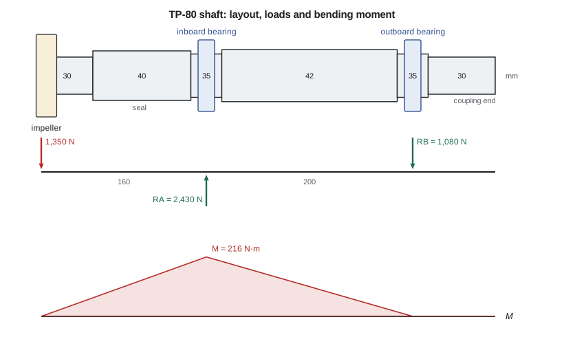
Good layouts keep shafts short, put heavy loads close to bearings, and avoid overhangs where possible. An end-suction pump cannot avoid the overhung impeller, which is why its geometry is so carefully standardized: the overhang, the distance between bearings and the shaft diameter at the seal together control both stress and deflection. A useful figure of merit, sometimes called the shaft flexibility factor, is the ratio of the overhang cubed to the fourth power of the diameter, \(L^3/D^4\); pump designers keep it below a value proven by experience, because deflection at the seal grows with it.
Loads, reactions and moments
Shaft loads come from the elements it carries. The TP-80 impeller produces a radial hydraulic load that is small at the best efficiency point and grows when the pump runs far from it; Farah uses a design value of 1,350 N including the impeller's weight, at the worst allowed operating point. The impeller also produces axial thrust, which balance holes reduce to about 600 N. The motor delivers torque through the coupling. With the impeller 160 mm from the inboard bearing and the bearings 200 mm apart, statics gives:
The outboard reaction acts downward, opposite to the inboard reaction: the shaft levers about the inboard bearing. The largest bending moment is at the inboard bearing, \(M = 1350 \times 0.160 = 216\) N·m, and the torque between the impeller and coupling is \(T = P/\omega = 59.7\) N·m. In general shafts carry loads in two planes, for example a gear's tangential and radial forces, and the moments in each plane are combined as \(M = \sqrt{M_y^2 + M_z^2}\) at each section.
Sizing for fatigue: the DE-Goodman equation
For a rotating shaft with steady torque and steady bending loads, the bending stress is fully reversed and the torsional stress is mean only. Substituting the equivalent stresses from Lesson 4 into the Goodman criterion and solving for the diameter gives the DE-Goodman equation:
Similar forms exist for the Gerber and ASME-elliptic criteria; the ASME-elliptic form is the basis of the withdrawn ANSI/ASME B106.1M shaft standard and is still widely quoted. Because \(K_f\) and \(S_e\) depend on the diameter through notch sensitivity and the size factor, the equation is applied with estimated values and the result checked after the diameter is chosen. For the TP-80 inboard shoulder with n = 2, the minimum diameter is 34.5 mm, so the 35 mm standard bearing seat is just adequate, consistent with the factor of 2.09 found in Lesson 4.
Each critical section must be checked: shoulders, keyways, grooves for retaining rings, and any section where the moment is large. On the TP-80 the impeller hub keyway is at a low-moment section, and the coupling keyway sees only torque, so the inboard shoulder governs the strength check. Keyways have high stress concentration factors, roughly 2.1 in bending and 3.0 in torsion for an end-milled keyseat with a sharp corner, so they are kept away from high-moment sections when possible.
Deflection and slope
A shaft that is strong enough can still be too flexible. Deflection at gears disturbs tooth contact, slope at bearings causes edge loading, and deflection at the seal faces of a pump opens the seal gap and wears the faces. Typical limits are:
| Location | Typical limit | Reason |
|---|---|---|
| Mechanical seal faces (process pumps) | 50 µm (0.002 in) at worst condition | Seal life |
| Spur gears | About 0.13 mm (0.005 in) deflection; slope under 0.5 mrad | Tooth contact |
| Deep-groove ball bearing | Slope roughly 1 to 3 mrad | Internal clearance and ball path |
| Cylindrical roller bearing | Slope roughly 0.5 to 1 mrad | Roller edge loading |
| Tapered roller bearing | Slope roughly 0.5 mrad | Roller edge loading |
Deflection of a stepped shaft is found by integrating the curvature \(M/(EI)\) twice along its length, with the second moment of area I changing at each step, and choosing the integration constants so that the deflection is zero at both bearings. The program does this numerically for the TP-80 layout. Finite element software does the same job for complex shafts, but a short numerical integration is fast, transparent and easy to check.
# TP-80 shaft: reactions, moments, DE-Goodman diameter, deflection, critical speed and key
import math
F_imp = 1350.0          # N, radial load at the overhung impeller (hydraulic plus weight)
xA, xB = 0.160, 0.360   # m, inboard and outboard bearings measured from the impeller
P, rpm = 11000.0, 1760  # W, rev/min
T = P / (2 * math.pi * rpm / 60)
RA = F_imp * xB / (xB - xA)          # inboard bearing reaction (up)
RB = RA - F_imp                       # outboard bearing reaction (down)
print(f"torque T = {T:.1f} N.m;  reactions RA = {RA:.0f} N, RB = {RB:.0f} N")
print(f"largest moment at the inboard bearing M = {F_imp*xA:.0f} N.m")

# DE-Goodman (ASME-style) minimum diameter at the bearing shoulder for n = 2
Se, Sut, Kf, Kfs, n = 178e6, 630e6, 1.57, 1.35, 2.0
Ma, Tm = F_imp * xA, T
d = (16 * n / math.pi * (2 * Kf * Ma / Se + math.sqrt(3) * Kfs * Tm / Sut)) ** (1 / 3)
print(f"DE-Goodman minimum diameter d = {d*1000:.1f} mm -> choose the 35 mm bearing seat")

# Deflection by numerical integration of M/(EI) along a stepped shaft
E = 207e9
def deflect(xA, xB, segs, F=F_imp, N=4400, L=0.440):
    RA = F * xB / (xB - xA); RB = RA - F
    def I_at(x):
        for a, b, dd in segs:
            if a <= x <= b: return math.pi * dd**4 / 64
        return math.pi * 0.030**4 / 64
    def M_at(x):                                   # sagging positive
        m = -F * x
        if x > xA: m += RA * (x - xA)
        if x > xB: m -= RB * (x - xB)
        return m
    h = L / N; xs = [i * h for i in range(N + 1)]
    k = [M_at(x) / (E * I_at(x)) for x in xs]
    slope = [0.0]; y = [0.0]
    for i in range(N): slope.append(slope[-1] + 0.5 * (k[i] + k[i + 1]) * h)
    for i in range(N): y.append(y[-1] + 0.5 * (slope[i] + slope[i + 1]) * h)
    iA, iB = round(xA / h), round(xB / h); c1 = (y[iB] - y[iA]) / (xB - xA)
    yy = [y[i] - (y[iA] + c1 * (x - xA)) for i, x in enumerate(xs)]
    return yy, (slope[iA] - c1), h
def segs_for(xA, xB):   # (from, to, diameter) in m: impeller hub, seal sleeve, bearing seats, frame span, coupling end
    return [(0.000, 0.050, 0.030), (0.050, xA - 0.015, 0.040), (xA - 0.015, xA + 0.015, 0.035),
            (xA + 0.015, xB - 0.015, 0.042), (xB - 0.015, xB + 0.015, 0.035), (xB + 0.015, 0.440, 0.030)]
yy, slA, h = deflect(xA, xB, segs_for(xA, xB))
iS = round(0.095 / h)
print(f"deflection at the seal faces (x = 95 mm) = {abs(yy[iS])*1e6:.0f} um")
print(f"deflection at the impeller = {abs(yy[0])*1e6:.0f} um; slope at inboard bearing = {abs(slA)*1000:.3f} mrad")
# Option: move the inboard bearing 25 mm closer to the impeller (shorter overhang)
yy2, slA2, _ = deflect(0.135, 0.335, segs_for(0.135, 0.335))
print(f"overhang 135 mm: seal faces {abs(yy2[iS])*1e6:.0f} um, impeller {abs(yy2[0])*1e6:.0f} um")

# First critical speed (Rayleigh) treating the impeller as the main mass
m_imp = 15.0                                       # kg, impeller
y_self = abs(yy[0]) * (m_imp * 9.81) / F_imp       # static sag under the impeller weight only
w = math.sqrt(9.81 / y_self)
print(f"first critical speed about {w*60/(2*math.pi):,.0f} rpm, ratio to running speed {w*60/(2*math.pi)/rpm:.1f}")

# Square key at the coupling, 8 x 7 mm on the 30 mm end, 1018 cold-drawn key steel (Sy = 370 MPa)
Fk = T / 0.015
Ssy = 0.577 * 370e6
for Lk in (0.020, 0.032, 0.040):
    n_shear = Ssy / (Fk / (0.008 * Lk)); n_crush = 370e6 / (Fk / (0.0035 * Lk))
print(f"key length {Lk*1000:.0f} mm: shear n = {n_shear:.1f}, bearing (crushing) n = {n_crush:.1f}")torque T = 59.7 N.m; reactions RA = 2430 N, RB = 1080 N largest moment at the inboard bearing M = 216 N.m DE-Goodman minimum diameter d = 34.5 mm -> choose the 35 mm bearing seat deflection at the seal faces (x = 95 mm) = 56 um deflection at the impeller = 177 um; slope at inboard bearing = 0.557 mrad overhang 135 mm: seal faces 26 um, impeller 120 um first critical speed about 6,800 rpm, ratio to running speed 3.9 key length 20 mm: shear n = 8.6, bearing (crushing) n = 6.5 key length 32 mm: shear n = 13.7, bearing (crushing) n = 10.4 key length 40 mm: shear n = 17.2, bearing (crushing) n = 13.0
Worked problem
Seal-face deflection of the first layout
The program finds a seal-face deflection of 56 µm with the first layout. Is it acceptable, and what change helps most?
Show solution
- The limit is 50 µm, so the first layout fails by about 12 percent.
- Raising the 40 mm seal section to 45 mm changes the result by only a few micrometres, because most of the deflection comes from the bending of the span and the slope at the inboard bearing.
- Moving the bearing frame 25 mm closer to the impeller, so the overhang is 135 mm, reduces the seal-face deflection to about 26 µm and the impeller deflection from 177 to 120 µm.
Answer: The overhang matters most, because deflection at the end of an overhang grows roughly with its cube. Farah shortens the overhang by redesigning the seal chamber cover, which also reduces the bending moment at the shoulder to 182 N·m and raises the fatigue factor of safety. This is why process pump standards limit the overhang and why newer pump designs use stiffer, shorter power ends.
Critical speed
A rotating shaft with a mass on it has natural frequencies of bending vibration. When the running speed matches one of them, any small unbalance excites a large whirling motion: this speed is a critical speed. Shafts are designed to run well below the first critical speed (a stiff shaft) or, in some high-speed machines, between critical speeds with careful balancing. A simple estimate for a shaft with one main mass is
where \(\delta_{st}\) is the static deflection under the mass's own weight. For several masses, Rayleigh's method gives \(\omega_c = \sqrt{g\sum m_i y_i / \sum m_i y_i^2}\). The TP-80's 15 kg impeller gives a first critical speed of about 6,800 rpm, nearly four times the running speed. Process pump practice usually asks for a first dry critical speed at least about 20 percent above the maximum running speed for a stiff shaft, so the TP-80 has ample margin. In a real pump the liquid in the wear-ring clearances adds stiffness and damping, which raises the wet critical speed further.
Keys
Keys transmit torque between a shaft and a hub. The most common is the parallel square or rectangular key, sized by shaft diameter from standard tables; its length is chosen to carry the torque. A key can fail by shearing across its width or by crushing (bearing failure) on its side faces. With a key of width w, height h and length L on a shaft of radius r, the force on the key is \(F = T/r\), and
The TP-80's coupling end is 30 mm, which takes an 8 × 7 mm key. With a key steel of 370 MPa yield strength, a 32 mm long key gives a factor of about 14 against shear and 10 against crushing. Keys are deliberately the weakest part of the joint in some designs, so that a jammed impeller shears the key rather than twisting the shaft, but in pumps the usual approach is to make the key strong and protect the drive with the motor's overload protection or a torque-limiting coupling. Other hub connections include splines, which carry more torque and allow sliding; interference fits, which avoid stress concentration from a keyway but are harder to dismantle; and tapered locking bushings, common on pulleys and sprockets.
Couplings
A coupling joins the pump shaft to the motor shaft. Rigid couplings require near-perfect alignment and are used only where the shafts are supported as one unit. Flexible couplings tolerate some misalignment: parallel offset, angular misalignment and axial movement. Common types for pumps are jaw couplings with an elastomer spider, which are cheap and damp shock; gear couplings, which carry high torque in a compact size; disc couplings, made from stacks of thin steel discs, which need no lubrication and have no backlash; and elastomeric tire couplings. Most process pumps use a spacer coupling, with a removable centre section that lets the seal and bearings be serviced without moving the motor.
Couplings are selected from catalogues by torque with a service factor for the driven machine (about 1.0 to 1.5 for centrifugal pumps, higher for reciprocating machines), by speed and by bore size. A flexible coupling does not cure misalignment; it only tolerates it. Misalignment beyond about a tenth of a millimetre at pump speeds puts reaction forces on the shafts and bearings and is a common cause of bearing failures. Laser alignment during installation is now standard practice.
Canadian occupational health and safety rules require guards on all exposed rotating shafts and couplings, and CSA Z432 gives the design requirements for those guards. Tidewater ships every TP-80 on a baseplate with a coupling guard that meets these rules and allows the alignment to be checked without removing it.
Common mistakes
MistakeSizing a shaft for stress only.
InsteadCheck deflection, slope and critical speed too; they often govern pump and gear shafts.
MistakePutting a keyway at a high-moment shoulder.
InsteadSeparate stress raisers and keep keyways at low-moment sections.
MistakeForgetting that the outboard reaction reverses for an overhung load.
InsteadDraw the free-body diagram; the shaft levers about the inboard bearing.
MistakeChoosing a coupling to fix misalignment.
InsteadAlign the shafts; flexible couplings only tolerate small residual misalignment.
MistakeIncreasing the diameter everywhere to reduce overhang deflection.
InsteadShorten the overhang; deflection grows roughly with its cube.
Summary and key terms
- A shaft layout locates elements with shoulders, keeps loads near bearings and steps diameters for assembly.
- For the TP-80, the overhung 1,350 N impeller load gives 216 N·m at the inboard bearing and reactions of 2,430 N and 1,080 N.
- The DE-Goodman equation gives a minimum diameter of 34.5 mm at the inboard shoulder, so the 35 mm seat is adequate.
- Deflection governs: the first layout's 56 µm at the seal exceeds the 50 µm limit; a 25 mm shorter overhang cuts it to 26 µm.
- The first critical speed is about 6,800 rpm, nearly four times the running speed.
- Keys are checked for shear and crushing; flexible couplings tolerate small misalignment but do not replace alignment.
- Shaft layout
- The arrangement of diameters, shoulders and elements along a shaft.
- Overhung load
- A load applied outside the span between bearings.
- DE-Goodman equation
- The shaft diameter equation from the distortion energy theory and the Goodman criterion.
- Critical speed
- A rotational speed equal to a natural frequency of shaft bending vibration.
- Rayleigh method
- An energy method for estimating the first natural frequency from static deflections.
- Parallel key
- A square or rectangular key that transmits torque between a shaft and hub.
- Spline
- A set of teeth on a shaft and hub that transmit torque and may allow sliding.
- Flexible coupling
- A coupling that transmits torque while tolerating small misalignment.
- Spacer coupling
- A flexible coupling with a removable centre section for servicing.
Practice problems
Work each problem on paper first, then reveal the answer to check.
A shaft carries 1,000 N at 100 mm outside a bearing span of 250 mm. Find the bearing reactions.
Show answer
1,400 N at the near bearing; 400 N in the opposite direction at the far bearing.
Use the DE-Goodman equation to find d for M_a = 150 N·m, T_m = 80 N·m, K_f = 1.6, K_fs = 1.4, S_e = 200 MPa, S_ut = 650 MPa and n = 2.
Show answer
About 30.2 mm.
A shaft's static deflection under a 20 kg rotor is 0.05 mm. Estimate the first critical speed.
Show answer
About 4,230 rpm.
In the program, change the overhang to 145 mm and the outboard bearing position accordingly. What is the seal-face deflection?
Show answer
About 37 µm.
A 10 × 8 mm key 40 mm long transmits 250 N·m on a 35 mm shaft. Find the shear stress.
Show answer
About 36 MPa.
Why do process pumps use spacer couplings?
Show answer
The seal and bearings can be removed without moving the motor, so alignment is kept.
Lesson quiz · 5 questions
Score 60% or more to complete this lesson.
Create a free account to save your progress, take quizzes and earn a certificate.