
MEC-330 · Lesson 7 of 12 · 27 min
Cogeneration and combined cycles
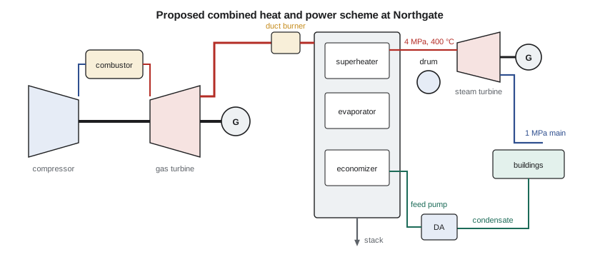
The first six lessons have built every piece Northgate needs for its main option. A gas turbine (Lesson 3) burns gas at high temperature and makes electricity; its exhaust, at about 445 °C, still carries most of the fuel energy. A heat-recovery steam generator (HRSG) can turn that exhaust into steam at Northgate's 4 MPa and 400 °C. The existing back-pressure turbine (Lesson 5) can expand that steam to the district main and make more electricity, and the district absorbs the rest as useful heat. This is cogeneration, or combined heat and power (CHP). Its close relative, the combined cycle, sends the steam to a condenser instead of a district system and is now the most efficient way to make electricity from fuel. In this lesson Elena's team designs Northgate's CHP scheme, finds its limits, and compares it with separate production of power and heat.
Cogeneration and its measures
A cogeneration plant produces electricity and useful heat from one fuel input. Because the heat is used rather than rejected, a much larger fraction of the fuel's energy does something useful. The simplest measure is the utilization factor,
which counts a kilowatt of heat the same as a kilowatt of electricity. That is a weakness: a plant that made nothing but low-temperature heat could score well. The power-to-heat ratio, \(\dot W/\dot Q\), tells the reader what kind of plant it is. A better comparison asks how much fuel the CHP plant saves compared with producing the same electricity in a reference power plant and the same heat in a reference boiler. The primary energy saving does exactly that:
where \(\eta_{el} = \dot W/\dot Q_{\text{fuel}}\) and \(\eta_{th} = \dot Q_{\text{useful}}/\dot Q_{\text{fuel}}\) are the plant's electrical and thermal efficiencies. Elena's team uses a modern gas-fired power plant at 45 percent and Northgate's own boilers at 85 percent as references. Exergy analysis (Lesson 1) gives the most honest measure of all, valuing the heat by its exergy, but PES is widely used because it is simple and needs no dead state.
The heat-recovery steam generator
An HRSG is a bank of heat exchangers in the exhaust duct of a gas turbine. Gas flows through a superheater, then an evaporator connected to a steam drum, then an economizer, while water flows the other way: feedwater is warmed in the economizer, boiled in the evaporator and superheated. Plotting temperature against heat transferred shows a sharp limit. The water boils at a constant temperature, 250.35 °C at 4 MPa, while the gas cools continuously. At the cold end of the evaporator, the gas temperature approaches the boiling temperature most closely; this smallest temperature difference is the pinch point, typically 8 to 15 K in practice.
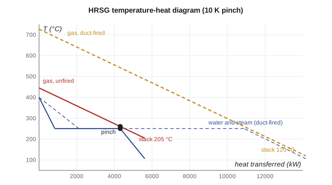
The pinch sets how much steam can be made. Heat given up by the gas between the turbine exhaust temperature and the pinch temperature must supply the superheater and evaporator:
Once the steam flow is known, the economizer balance gives the stack temperature. A high steam pressure means a high boiling temperature, a high pinch temperature and therefore little steam and a hot stack. Plants solve this with two or three pressure levels, each with its own evaporator, or with supplementary firing in a duct burner, which raises the gas temperature ahead of the HRSG. The duct burner uses the oxygen left in the gas turbine exhaust, which typically contains 13 to 15 percent oxygen by volume, so it needs no extra air and its added fuel goes almost entirely into the steam.
Designing Northgate's CHP scheme
The program takes the candidate turbine of Lesson 3 at its rating condition: 21.6 kg/s of exhaust at 718 K, 6 MW of output and a real efficiency of 34 percent. The exhaust gas specific heat is taken as 1.08 kJ/kg·K, higher than that of air because of the carbon dioxide and water vapour it contains. The HRSG makes 4 MPa, 400 °C steam with a 10 K pinch from feedwater at 445.1 kJ/kg, and the steam goes to the existing back-pressure turbine and then to the district.
# Northgate combined heat and power: gas turbine + heat-recovery steam generator + existing back-pressure turbine
cp_g = 1.08                        # exhaust gas specific heat, kJ/kg K
m_g, T_ex = 21.6, 718.3            # exhaust flow (kg/s) and temperature (K) from Lesson 3 at 15 C
W_gt, eta_gt = 6000.0, 0.34        # net output (kW) and real efficiency on LHV
fuel_gt = W_gt / eta_gt

# Steam side: 4 MPa, 400 C from feedwater at 445.1 kJ/kg; saturation at 4 MPa is 250.35 C, hf = 1087.3
h_sh, h_f4, h_fw, T_sat = 3214.5, 1087.3, 445.1, 250.35 + 273.15
pinch = 10.0

def hrsg(T_in):
    """Steam made and stack temperature for gas entering at T_in (K)."""
    T_p = T_sat + pinch                                        # gas leaving the evaporator
    m_s = m_g * cp_g * (T_in - T_p) / (h_sh - h_f4)            # superheater + evaporator
    T_stack = T_p - m_s * (h_f4 - h_fw) / (m_g * cp_g)         # economizer
    return m_s, T_stack

h_bp, h_ret = 2943.1, 356.0          # back-pressure exhaust to the main; condensate return from buildings
for label, T_in in (("unfired", T_ex), ("duct-fired to 1000 K", 1000.0)):
    m_s, T_stack = hrsg(T_in)
    fuel_duct = m_g * cp_g * (T_in - T_ex)                    # duct burner uses oxygen left in the exhaust
    fuel = fuel_gt + fuel_duct
    W_st = m_s * (h_sh - h_bp) * 0.96
    Q = m_s * (h_bp - h_ret) - 300                             # heat to buildings less about 300 kW of losses
    W = W_gt + W_st
    eu = (W + Q) / fuel
    pes = 1 - 1 / ((W / fuel) / 0.45 + (Q / fuel) / 0.85)      # against a 45 % power plant and an 85 % boiler
    print(f"{label:21s}: steam {m_s:4.2f} kg/s, stack {T_stack - 273.15:5.1f} C, fuel {fuel:6.0f} kW,"
          f" power {W:5.0f} kW, heat {Q:5.0f} kW")
    print(f"{'':21s}  utilization factor {eu:.3f}, power-to-heat ratio {W / Q:.2f}, primary energy saving {pes:.3f}")

# Combined cycle (condensing) efficiency estimate
for eta_g, eff_hrsg, eta_s in ((0.34, 0.80, 0.30), (0.40, 0.85, 0.35), (0.42, 0.88, 0.38)):
print(f"gas {eta_g:.2f}, HRSG recovery {eff_hrsg:.2f}, steam {eta_s:.2f} -> combined {eta_g + (1 - eta_g) * eff_hrsg * eta_s:.3f}")unfired : steam 2.03 kg/s, stack 204.6 C, fuel 17647 kW, power 6528 kW, heat 4943 kW
utilization factor 0.650, power-to-heat ratio 1.32, primary energy saving 0.132
duct-fired to 1000 K : steam 5.12 kg/s, stack 119.5 C, fuel 24219 kW, power 7333 kW, heat 12935 kW
utilization factor 0.837, power-to-heat ratio 0.57, primary energy saving 0.231
gas 0.34, HRSG recovery 0.80, steam 0.30 -> combined 0.498
gas 0.40, HRSG recovery 0.85, steam 0.35 -> combined 0.579
gas 0.42, HRSG recovery 0.88, steam 0.38 -> combined 0.614Worked problem
The unfired HRSG
Exhaust at 718.3 K flows at 21.6 kg/s with \(c_{p,g} = 1.08\) kJ/kg·K. Steam is made at 4 MPa and 400 °C (\(h = 3214.5\); saturated liquid at 4 MPa \(h_f = 1087.3\); \(T_{sat} = 250.35\) °C) from feedwater at \(h = 445.1\), with a 10 K pinch. Find the steam flow and the stack temperature.
Show solution
- Pinch: gas leaves the evaporator at \(250.35 + 10 = 260.35\) °C (533.5 K).
- Superheater and evaporator: \(\dot m_s = 21.6(1.08)(718.3 - 533.5)/(3214.5 - 1087.3) = 2.03\) kg/s.
- Economizer: gas temperature drop \(= 2.03(1087.3 - 445.1)/(21.6 \times 1.08) = 55.8\) K.
- \[T_{\text{stack}} = 260.35 - 55.8 = 204.6\ \text{°C}\]
Answer: Only 2 kg/s of steam, and the stack is still at 205 °C. The exhaust at 445 °C is not much hotter than the 400 °C steam it must make, and the 250 °C boiling plateau blocks the rest of the heat. The scheme would deliver about 6.5 MW of electricity and 4.9 MW of heat, a utilization factor of 0.65.
The team considers two fixes. A low-temperature economizer heating district return water could cool the stack from 205 °C to about 90 °C and recover roughly \(21.6 \times 1.08 \times 115 \approx 2700\) kW more heat, which Northgate can use most of the winter. A duct burner raising the gas to 1000 K (727 °C) changes the picture more: the steam flow rises to 5.1 kg/s, the stack falls to 120 °C, and the plant delivers 7.3 MW of electricity and 12.9 MW of heat from 24.2 MW of fuel.
Worked problem
Utilization factor and primary energy saving with duct firing
With duct firing, the program finds 24,219 kW of fuel, 7,333 kW of electricity and 12,935 kW of heat delivered. Find the utilization factor, the power-to-heat ratio and the primary energy saving against a 45 percent power plant and an 85 percent boiler.
Show solution
- \(\varepsilon_u = (7333 + 12{,}935)/24{,}219 = 0.837\); power-to-heat ratio \(= 7333/12{,}935 = 0.57\).
- \(\eta_{el} = 7333/24{,}219 = 0.303\); \(\eta_{th} = 12{,}935/24{,}219 = 0.534\).
- \[\text{PES} = 1 - \frac{1}{0.303/0.45 + 0.534/0.85} = 1 - \frac{1}{0.673 + 0.628} = 0.231\]
Answer: Separate production of the same electricity and heat would need 23 percent more fuel. The unfired case, with its hot stack, saves only 13 percent. Duct firing looks inefficient at first, because the extra fuel makes only heat, but it uses the turbine's spare oxygen and lets the HRSG recover far more of the exhaust.
Matching the plant to the load
A district system's heat load varies by a factor of five or more between a January night and a July afternoon. A CHP plant earns its fuel savings only when its heat is used, so it is usually sized for the base heat load, the level exceeded most hours of the year, with the existing boilers covering the peaks. Elena's team plots Northgate's hourly heat demand for a typical year as a load duration curve and finds that the duct-fired scheme's 12.9 MW of heat would be fully used for about 5,000 hours a year. In summer the duct burner would be turned off and the unfired HRSG's 4.9 MW of heat matched to the reduced load; for the lowest summer loads, the turbine might run only in daytime peak-price hours.
Thermal storage helps. A large insulated tank of hot water lets a CHP plant run when electricity is valuable and store the heat for later, which is common in district systems in northern Europe. Northgate's steam network makes storage harder than in a hot-water system, another reason the study flags conversion to hot water as a long-term option.
Combined cycles
In a combined-cycle power plant, the HRSG's steam goes to a condensing steam turbine. The gas turbine operates as the topping cycle, adding heat at very high temperature; the steam cycle operates as the bottoming cycle, rejecting heat at the condenser temperature. If the gas turbine efficiency is \(\eta_g\), the HRSG recovers a fraction \(\varepsilon_H\) of the exhaust heat and the steam cycle converts a fraction \(\eta_s\) of that to work, the combined efficiency is
The program's last lines evaluate it. A small machine like Northgate's (0.34, 0.80, 0.30) gives about 0.50; a large modern plant with a 40 percent gas turbine, a three-pressure HRSG with reheat and a 35 to 38 percent steam cycle gives 0.58 to 0.61. The best large combined-cycle plants now exceed 60 percent and approach 64 percent on the lower heating value, with gas turbine inlet temperatures near 1600 °C or higher. No other heat engine using fuel comes close; the combination works because the gas turbine adds heat at high temperature and the steam cycle rejects heat at low temperature, so together they span almost the whole available range.
Worked problem
A combined-cycle estimate
A gas turbine with an efficiency of 0.40 exhausts into an HRSG that recovers 85 percent of the exhaust heat for a steam cycle with an efficiency of 0.35. Find the combined efficiency and the share of the output from each cycle.
Show solution
- \[\eta_{cc} = 0.40 + (1 - 0.40)(0.85)(0.35) = 0.40 + 0.179 = 0.579\]
- Gas turbine share: \(0.40/0.579 = 69\) percent; steam turbine share: 31 percent.
Answer: About 58 percent, with roughly two thirds of the output from the gas turbine, a typical split. The steam cycle in a combined-cycle plant is simpler than a utility Rankine plant: it uses no feedwater heaters, because the HRSG's economizer recovers the low-temperature exhaust heat that feedwater heaters would otherwise supply.
Exergy and fairness between products
How should the fuel be divided between the electricity and the heat? The question matters for pricing heat to Northgate's customers and for reporting emissions per unit of each product. An energy-based split charges heat and electricity equally per kilowatt-hour, which overcharges heat. An exergy-based split charges each product in proportion to its exergy, so a kilowatt of electricity carries the same fuel share as a kilowatt of exergy in steam. Since Northgate's district steam carries about 883 kJ/kg of exergy for about 2587 kJ/kg of useful heat (Lesson 1), heat delivered as steam bears roughly a third of the fuel burden per unit that electricity does. Regulators in different places use different rules, and the choice changes the reported carbon intensity of district heat considerably.
In Canada, CHP projects are assessed provincially. In Manitoba, where the grid is nearly all hydroelectric, a gas CHP plant saves fuel compared with separate gas-fired production but displaces very low-carbon electricity, so its emissions benefit is small or negative; the team records this as a key issue for Lesson 12.
Common mistakes
MistakeTreating the utilization factor as a thermal efficiency.
InsteadIt counts useful heat equally with electricity; use PES or exergy for a fair comparison.
MistakeIgnoring the pinch in an HRSG.
InsteadThe pinch at the evaporator's cold end limits steam production at a given pressure.
MistakeAssuming duct firing wastes fuel.
InsteadDuct burners use exhaust oxygen and convert almost all their fuel to steam, and they lower the stack temperature.
MistakeSizing CHP for the peak heat load.
InsteadSize for the base load that is used most hours; boilers cover peaks.
MistakeAdding feedwater heaters to the steam side of a combined cycle.
InsteadThe HRSG economizer uses exhaust heat for the same job more effectively.
Summary and key terms
- Cogeneration produces electricity and useful heat from one fuel; the utilization factor counts both.
- Primary energy saving compares CHP with separate production in reference plants.
- In an HRSG, the pinch at the cold end of the evaporator limits steam production; multiple pressures or duct firing raise recovery.
- Duct firing uses the oxygen left in gas turbine exhaust.
- Combined-cycle efficiency: η_cc = η_g + (1 − η_g)ε_Hη_s; the best plants exceed 60 percent.
- CHP should be sized for the base heat load and judged against the electricity it displaces.
- Cogeneration
- The combined production of electricity and useful heat from one fuel input; also called combined heat and power (CHP).
- Utilization factor
- The ratio of electricity plus useful heat to fuel energy.
- Power-to-heat ratio
- The ratio of electricity output to useful heat output of a CHP plant.
- Primary energy saving
- The fraction of fuel saved by CHP compared with separate production of the same products.
- Heat-recovery steam generator
- A heat exchanger in a gas turbine exhaust that raises steam.
- Pinch point
- The smallest temperature difference between gas and water in an HRSG, at the cold end of the evaporator.
- Duct firing
- Burning extra fuel in the gas turbine exhaust ahead of the HRSG; also called supplementary firing.
- Combined cycle
- A power plant with a gas turbine topping cycle and a steam bottoming cycle.
- Topping cycle
- The higher-temperature cycle in a combined plant.
- Load duration curve
- A plot of demand sorted from highest to lowest over a year, showing how many hours each level is exceeded.
Practice problems
Work each problem on paper first, then reveal the answer to check.
A CHP plant burns 40 MW of fuel and delivers 14 MW of electricity and 18 MW of heat. Find its utilization factor.
Show answer
0.80.
For the plant in the previous question, find the PES against 0.45 and 0.85 references.
Show answer
About 0.23.
In the unfired HRSG, what pinch would allow 2.2 kg/s of steam?
Show answer
None: the gas would have to leave the evaporator at about 245 °C, below the 250 °C boiling temperature, so 2.2 kg/s cannot be made at 4 MPa without duct firing.
In the program, raise the pinch to 15 K for the duct-fired case. What steam flow results?
Show answer
About 5.06 kg/s.
Find the combined efficiency for η_g = 0.38, ε_H = 0.9 and η_s = 0.36.
Show answer
About 0.581.
Why does a combined cycle beat either cycle alone?
Show answer
The gas turbine adds heat at high temperature and the steam cycle rejects it at low temperature, spanning the whole range.
Lesson quiz · 5 questions
Score 60% or more to complete this lesson.
Create a free account to save your progress, take quizzes and earn a certificate.