
MEC-330 · Lesson 2 of 12 · 29 min
Reciprocating engines: the Otto and Diesel cycles
Lesson 1 showed that Northgate's boilers destroy two thirds of the fuel's exergy. One way to use that exergy is to burn the gas first in an engine that makes electricity and then recover the engine's waste heat. Kofi Mensah's first proposal is a pair of large natural-gas engines driving generators, with their jacket water and exhaust heat feeding the district system. Northgate already has a diesel engine: a 1.5 MW standby generator that can start the plant during a power failure. In this lesson we model both engines with air-standard cycles, the idealizations that let us see how compression ratio, heat addition and gas properties set an engine's efficiency.
Gas power cycles and the air-standard assumptions
In an internal-combustion engine the working fluid is not taken around a closed cycle: air and fuel enter, burn and leave as exhaust. To analyze it as a cycle we make the air-standard assumptions. The working fluid is air, treated as an ideal gas, circulating in a closed loop. All processes are internally reversible. Combustion is replaced by heat addition from an external source, and the exhaust and intake strokes are replaced by heat rejection that returns the air to its initial state. When we also take the specific heats as constant at their room-temperature values (\(c_p = 1.005\), \(c_v = 0.718\) kJ/kg·K, \(k = 1.4\)), we have the cold-air-standard assumptions.
These models overestimate efficiency, sometimes by a wide margin, but they get the trends right and they are simple enough to show cause and effect. We then refine them with specific heats that vary with temperature, which brings the numbers closer to real engines.
A few terms describe reciprocating engines. The piston moves between top dead centre (TDC), where the cylinder volume is smallest, and bottom dead centre (BDC), where it is largest. The displacement volume is the volume swept by the piston, and the compression ratio is
The mean effective pressure (MEP) is the constant pressure that, acting on the piston for the whole power stroke, would produce the same net work as the actual cycle:
MEP lets engines of different sizes be compared. For a four-stroke engine, which completes one cycle every two revolutions, the power is \(\dot W = \text{MEP} \cdot V_d \cdot N/2\) with \(N\) in revolutions per second. When the MEP is calculated from the measured shaft output it is called the brake mean effective pressure.
The Otto cycle
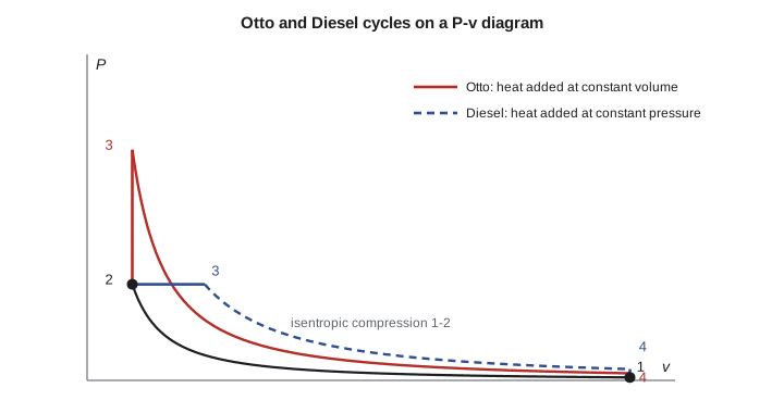
The Otto cycle models the spark-ignition engine. It has four internally reversible processes: (1-2) isentropic compression, (2-3) heat addition at constant volume, which represents rapid combustion at top dead centre, (3-4) isentropic expansion, and (4-1) heat rejection at constant volume. With constant specific heats, \(q_{\text{in}} = c_v(T_3 - T_2)\) and \(q_{\text{out}} = c_v(T_4 - T_1)\). Because the two isentropic processes span the same volume ratio, \(T_2/T_1 = T_3/T_4 = r^{k-1}\), and the thermal efficiency reduces to
The efficiency depends only on the compression ratio and the ratio of specific heats. It rises quickly at first and then levels off: from 0.565 at \(r = 8\) to 0.630 at \(r = 12\) and 0.698 at \(r = 20\). In a spark-ignition engine the compression ratio is limited by knock, the autoignition of the unburned mixture ahead of the flame, which produces pressure waves that can damage the engine. Gasoline car engines run at compression ratios of about 9 to 13. Large natural-gas engines for power generation run lean, with about twice the air needed for complete combustion, which lowers combustion temperatures and nitrogen oxide formation and lets them use compression ratios of roughly 11 to 13 with turbocharging.
The ratio of specific heats matters too. A gas with higher \(k\) gives a higher efficiency for the same compression ratio, which is one reason lean mixtures, closer to pure air, are more efficient than rich ones. Real combustion products have lower \(k\) than cold air, and \(k\) falls further as temperature rises, so real engines fall below the cold-air-standard value.
The Diesel cycle
In a compression-ignition engine, air alone is compressed to a temperature above the fuel's autoignition point, and fuel is injected near top dead centre. Combustion continues as the piston begins to move down, so the Diesel cycle models it as heat addition at constant pressure. The cutoff ratio \(r_c = V_3/V_2\) measures how long heat addition lasts. With constant specific heats, \(q_{\text{in}} = c_p(T_3 - T_2)\) and \(q_{\text{out}} = c_v(T_4 - T_1)\), and
The bracketed term is always greater than one, so for the same compression ratio the Diesel cycle is less efficient than the Otto cycle. But diesel engines do not knock, because only air is compressed, and they run at compression ratios of about 14 to 22. At those ratios they are more efficient than spark-ignition engines at their lower ratios. A larger cutoff ratio, meaning more fuel injected and more power, lowers efficiency.
Real engines lie between the two models: combustion in a fast diesel is partly at constant volume and partly at constant pressure. The dual cycle captures this by splitting the heat addition into a constant-volume part followed by a constant-pressure part. With the pressure ratio of the constant-volume part equal to one it becomes the Diesel cycle; with the cutoff ratio equal to one it becomes the Otto cycle.
Modelling Northgate's engines
The program evaluates both formulas over a range of compression ratios. It then models Kofi's gas engine with specific heats that vary with temperature, using a cubic fit for \(c_p\) of air, and compares the result with the cold-air-standard numbers. Finally it sizes the engine and checks the standby diesel.
# Otto and Diesel cycles: cold-air-standard formulas, then air with temperature-dependent specific heats
import math
k, cp, cv, R = 1.4, 1.005, 0.718, 0.287          # cold-air-standard values, kJ/kg K

def otto_eff(r): return 1 - r ** (1 - k)
def diesel_eff(r, rc): return 1 - r ** (1 - k) * (rc ** k - 1) / (k * (rc - 1))

print("cold-air-standard efficiencies")
for r in (8, 10, 12, 16, 20):
    print(f"  r = {r:2d}: Otto {otto_eff(r):.3f}   Diesel (rc = 2) {diesel_eff(r, 2):.3f}")

# Air with cp(T) = a + bT + cT^2 + dT^3 in kJ/kmol K (valid about 273 to 1800 K)
a, b, c, d, M = 28.11, 0.1967e-2, 0.4802e-5, -1.966e-9, 28.97
def h(T): return (a*T + b*T**2/2 + c*T**3/3 + d*T**4/4) / M          # kJ/kg, arbitrary zero
def u(T): return h(T) - R * T
def s0(T): return (a*math.log(T) + b*T + c*T**2/2 + d*T**3/3) / M   # kJ/kg K, arbitrary zero
def solve(f, lo, hi):
    for _ in range(100):
        m = (lo + hi) / 2
        lo, hi = (m, hi) if f(lo) * f(m) > 0 else (lo, m)
    return (lo + hi) / 2

def otto(r, T1, P1, qin):
    T2 = solve(lambda T: s0(T) - s0(T1) - R * math.log(T * r / T1), T1, 3000)   # isentropic, v1/v2 = r
    T3 = solve(lambda T: u(T) - u(T2) - qin, T2, 4000)                         # constant volume heat addition
    T4 = solve(lambda T: s0(T3) - s0(T) - R * math.log(T3 * r / T), 200, T3)    # isentropic expansion
    w = (u(T3) - u(T4)) - (u(T2) - u(T1))
    v1 = R * T1 / P1
    mep = w / (v1 * (1 - 1 / r))
    return T2, T3, T4, w / qin, mep

print("\ngas engine (Otto), r = 12, after turbocharger and intercooler: 300 kPa, 320 K, qin = 1200 kJ/kg")
T2, T3, T4, eta, mep = otto(12, 320, 300, 1200)
print(f"  variable cp: T2 = {T2:.0f} K, T3 = {T3:.0f} K, T4 = {T4:.0f} K, eta = {eta:.3f}, MEP = {mep:.0f} kPa")
T2c = 320 * 12 ** 0.4; T3c = T2c + 1200 / cv; T4c = T3c / 12 ** 0.4
print(f"  constant cp: T2 = {T2c:.0f} K, T3 = {T3c:.0f} K, T4 = {T4c:.0f} K, eta = {otto_eff(12):.3f}")

# Engine size: 16 cylinders, bore 170 mm, stroke 210 mm, four-stroke at 1500 rpm
n_cyl, bore, stroke, rpm = 16, 0.170, 0.210, 1500
Vd = n_cyl * math.pi / 4 * bore ** 2 * stroke           # m^3
bmep_needed = 2000 * 2 * 60 / (Vd * rpm)                # kPa for 2000 kW of shaft power
print(f"\ndisplacement {Vd * 1000:.1f} L; brake MEP for 2.0 MW at 1500 rpm = {bmep_needed:.0f} kPa")

# Standby diesel (cold-air standard): r = 17, 100 kPa and 300 K, qin = 1500 kJ/kg at constant pressure
r, T1, qin = 17, 300.0, 1500.0
T2 = T1 * r ** (k - 1); T3 = T2 + qin / cp; rc = T3 / T2
T4 = T3 * (rc / r) ** (k - 1); qout = cv * (T4 - T1)
print(f"\nstandby diesel: T2 = {T2:.0f} K, T3 = {T3:.0f} K, rc = {rc:.2f}, T4 = {T4:.0f} K, eta = {1 - qout / qin:.3f} (formula {diesel_eff(r, rc):.3f})")cold-air-standard efficiencies r = 8: Otto 0.565 Diesel (rc = 2) 0.490 r = 10: Otto 0.602 Diesel (rc = 2) 0.534 r = 12: Otto 0.630 Diesel (rc = 2) 0.567 r = 16: Otto 0.670 Diesel (rc = 2) 0.614 r = 20: Otto 0.698 Diesel (rc = 2) 0.647 gas engine (Otto), r = 12, after turbocharger and intercooler: 300 kPa, 320 K, qin = 1200 kJ/kg variable cp: T2 = 821 K, T3 = 2143 K, T4 = 980 K, eta = 0.571, MEP = 2441 kPa constant cp: T2 = 865 K, T3 = 2536 K, T4 = 939 K, eta = 0.630 displacement 76.3 L; brake MEP for 2.0 MW at 1500 rpm = 2098 kPa standby diesel: T2 = 932 K, T3 = 2424 K, rc = 2.60, T4 = 1144 K, eta = 0.596 (formula 0.596)
Worked problem
The gas engine as an Otto cycle
After the turbocharger and intercooler, the mixture enters the cylinder at 300 kPa and 320 K. The compression ratio is 12 and the heat added, after allowing for heat lost to the cylinder walls, is equivalent to 1200 kJ per kilogram of air. Find the temperatures and thermal efficiency using cold-air-standard properties.
Show solution
- Compression: \(T_2 = 320(12)^{0.4} = 865\) K.
- Heat addition at constant volume: \(T_3 = 865 + 1200/0.718 = 2536\) K.
- Expansion: \(T_4 = 2536/12^{0.4} = 939\) K.
- \[\eta = 1 - \frac{T_4 - T_1}{T_3 - T_2} = 1 - \frac{939 - 320}{2536 - 865} = 0.630\]
Answer: The cold-air standard gives 63 percent and a peak temperature of about 2540 K. With variable specific heats the program finds a peak of about 2140 K and an efficiency of 0.571, because the specific heat of air rises with temperature: the same heat raises the temperature less, and the expansion recovers less of it. (The \(c_p\) fit is stated for temperatures up to about 1800 K, so the peak is a slight extrapolation, adequate for this comparison.)
Neither number is the efficiency Northgate would see. Real engines lose heat to the cylinder walls during compression and expansion, burn over a finite time rather than instantly, pump gas in and out through valves, and lose work to friction and auxiliaries. The best large lean-burn gas engines convert roughly 45 to nearly 50 percent of the fuel energy to electricity, about four fifths of the variable-specific-heat air-standard value. The remaining half of the fuel energy appears as heat in the exhaust, at about 400 to 500 °C, and in the jacket water, lubricating oil and intercooler at 40 to 95 °C. That heat is what makes an engine attractive for cogeneration: Northgate could use the exhaust to raise steam and the jacket water to preheat feedwater or district return water.
Worked problem
Sizing the engine with mean effective pressure
Kofi's candidate engine has 16 cylinders with a bore of 170 mm and a stroke of 210 mm and runs at 1500 rpm on a four-stroke cycle. What brake mean effective pressure must it develop for 2.0 MW of shaft power?
Show solution
- Displacement: \(V_d = 16 \cdot \tfrac{\pi}{4}(0.170)^2(0.210) = 0.0763\ \text{m}^3\) (76.3 L).
- Four-stroke: cycles per second \(= 1500/(2 \cdot 60) = 12.5\).
- \[\text{BMEP} = \frac{\dot W}{V_d \cdot N/2} = \frac{2000}{0.0763 \times 12.5} = 2098\ \text{kPa}\]
Answer: About 2.1 MPa, a typical value for modern turbocharged gas engines. The air-standard MEP of the variable-specific-heat cycle is 2.44 MPa; the brake value is lower because of friction and the real-cycle losses. Two such engines would supply about 3.9 MW of electricity with a generator efficiency near 97 percent.
Worked problem
The standby diesel
Model the standby diesel with the cold-air standard: compression ratio 17, intake at 100 kPa and 300 K, and 1500 kJ/kg of heat added at constant pressure. Find the cutoff ratio and the thermal efficiency.
Show solution
- \(T_2 = 300(17)^{0.4} = 932\) K.
- \(T_3 = 932 + 1500/1.005 = 2424\) K; \(r_c = T_3/T_2 = 2.60\).
- \(T_4 = T_3 (r_c/r)^{k-1} = 2424(2.60/17)^{0.4} = 1144\) K; \(q_{\text{out}} = 0.718(1144 - 300) = 606\) kJ/kg.
- \[\eta = 1 - \frac{606}{1500} = 0.596\]
Answer: About 60 percent by the formula. The diesel has a higher compression ratio than the gas engine but a lower ideal efficiency, because its heat is added over a long cutoff. In service the standby engine runs only for tests and emergencies, so its efficiency matters less than its reliability and start-up time.
From ideal cycles to real engines
Engine designers use several ideas that come straight out of the cycle analysis. Raising the compression ratio raises efficiency until knock or peak pressures limit it. Turbocharging raises the intake pressure and therefore the mass of air in each cycle, which raises the MEP and power from a given engine size; intercooling the compressed air keeps \(T_1\) low, which lowers the compression work and the risk of knock. Running lean raises \(k\) and lowers peak temperatures. The Miller cycle, now common in large gas engines, closes the intake valve early or late so that the effective compression ratio is lower than the expansion ratio: the engine expands its gases further than it compresses them, which recovers more work and lowers combustion temperatures. The Atkinson cycle, used in some hybrid cars, is the same idea.
Exergy analysis puts the remaining losses in order. The largest is combustion itself, which in any engine destroys a fifth to a third of the fuel exergy. Next come the exergy carried out with the hot exhaust and the heat to the cooling water. Cogeneration recovers much of the exhaust and cooling-water energy, but because the cooling water is below 100 °C, it carries little exergy, which is why an engine with heat recovery still has a second-law efficiency well below its energy-based utilization factor.
Stirling and Ericsson cycles
Two other cycles reach the Carnot efficiency in principle. The Stirling cycle has two isothermal processes and two constant-volume processes, and the Ericsson cycle has two isothermal and two constant-pressure processes. In both, a regenerator stores heat given up in one of the non-isothermal processes and returns it in the other, so all external heat is added and rejected isothermally. Stirling engines are external-combustion engines, which lets them run on any heat source, including solar collectors and biomass, but they are hard to build at large sizes. The ideas matter for this course because regeneration, returning internal heat within a cycle, reappears in gas turbines (Lesson 3) and steam plants (Lesson 6).
In Canada, emissions from stationary gas engines are covered by federal multi-sector air pollutant rules that limit nitrogen oxides from new and existing engines, and provinces add their own permits. Northgate's air permit application would need to show the engines' NOx emissions, which is another reason lean-burn engines are favoured.
Elena's summary for the study is short. Two gas engines would supply about 3.9 MW of electricity at roughly 45 percent efficiency, with a little under half the fuel energy recoverable as heat. They start quickly, follow load well and keep high efficiency at part load, which suits a district system whose demand swings every day. Their weaknesses are maintenance, which scales with running hours, and the low temperature of much of their waste heat. Lesson 3 examines the alternative, a gas turbine, whose waste heat is hotter and comes in a single exhaust stream.
For US customary units, the same cycle formulas apply with temperatures in rankine and specific heats of 0.240 and 0.171 Btu/lbm·R; MEP is often quoted in psi, and 2.1 MPa is about 300 psi.
Common mistakes
MistakeUsing the Otto efficiency formula for a diesel engine.
InsteadThe Diesel formula includes the cutoff ratio term, which lowers efficiency for a given r.
MistakeTaking the cold-air-standard efficiency as a realistic engine efficiency.
InsteadIt is an upper trend line; real engines reach about four fifths of the variable-specific-heat value.
MistakeUsing c_p for constant-volume heat addition.
InsteadConstant-volume heat addition uses c_v; constant-pressure uses c_p.
MistakeForgetting that a four-stroke engine fires once every two revolutions.
InsteadPower = MEP · V_d · N/2 for four-stroke engines.
MistakeAssuming a higher compression ratio always helps a spark-ignition engine.
InsteadKnock limits the compression ratio of spark-ignition engines.
Summary and key terms
- Air-standard cycles model engines as closed cycles of air with heat addition replacing combustion; cold-air-standard cycles also take specific heats as constant.
- Compression ratio r = V_max/V_min; MEP = w_net/(v₁(1 − 1/r)); power = MEP · V_d · N/2 for four-stroke engines.
- Otto cycle: heat added at constant volume; η = 1 − 1/r^(k−1).
- Diesel cycle: heat added at constant pressure; η is lower than Otto at the same r but diesels run at higher r.
- Temperature-dependent specific heats lower the predicted peak temperature and efficiency.
- Turbocharging, intercooling, lean burn and the Miller cycle raise real engine efficiency and power.
- Large gas engines reach roughly 45 to nearly 50 percent electrical efficiency, with the rest of the energy available as exhaust and cooling-water heat.
- Air-standard assumptions
- Modelling an engine as a closed, internally reversible cycle of air with external heat addition and rejection.
- Compression ratio
- The ratio of maximum to minimum cylinder volume.
- Mean effective pressure
- The constant pressure that would produce the cycle net work over one piston displacement.
- Otto cycle
- The ideal cycle for spark-ignition engines, with heat added at constant volume.
- Diesel cycle
- The ideal cycle for compression-ignition engines, with heat added at constant pressure.
- Cutoff ratio
- The ratio of cylinder volumes after and before constant-pressure heat addition in the Diesel cycle.
- Knock
- Autoignition of the unburned mixture in a spark-ignition engine, which limits its compression ratio.
- Dual cycle
- A model with heat added partly at constant volume and partly at constant pressure.
- Miller cycle
- An engine cycle with an effective compression ratio lower than its expansion ratio.
- Stirling cycle
- An ideal regenerative cycle with two isothermal and two constant-volume processes.
Practice problems
Work each problem on paper first, then reveal the answer to check.
Find the cold-air-standard Otto efficiency at r = 9.
Show answer
0.585.
An Otto cycle at r = 10 starts at 100 kPa and 300 K and receives 900 kJ/kg. Find T₃ with constant specific heats.
Show answer
About 2007 K (T₂ = 754 K).
Find the Diesel efficiency at r = 18 and r_c = 2.2.
Show answer
About 0.622.
A four-stroke engine of 12 L displacement at 1800 rpm develops 1.4 MPa BMEP. Find its power.
Show answer
252 kW.
In the program, change the gas engine's compression ratio to 13. What does the variable-specific-heat efficiency become?
Show answer
About 0.582.
Why does a diesel engine not knock?
Show answer
Only air is compressed; fuel is injected when combustion is wanted.
Lesson quiz · 5 questions
Score 60% or more to complete this lesson.
Create a free account to save your progress, take quizzes and earn a certificate.