
LVT-130 · Lesson 9 of 12 · 19 min
Wiremap, continuity and verification testing
Testing on a cabling job happens at three levels. Verification checks that each link is wired correctly, conductor by conductor. Qualification checks whether an existing link can carry a particular network application, such as 1 or 10 gigabit Ethernet. Certification measures each link's transmission performance across the full frequency range of its category and compares it with the limits in the standard. The sixth floor's acceptance requires certification of every link, which lesson 10 covers. This lesson covers verification, because it is the test the crew uses every day, and the wiremap, because every certification test starts with one.
Three tiers of test equipment
Verification testers are small and inexpensive: a main unit and a remote, or a set of numbered remotes, that check continuity and the wiremap, often with a length estimate and a tone generator for tracing cables. Qualification testers send real network traffic or measure signal quality to report whether a link will support a given speed; they are used on existing cabling and for troubleshooting, but they do not certify new installations and their results are not accepted for warranties. Certification testers make swept-frequency measurements of every parameter in TIA-568.2 or ISO/IEC 11801 and report PASS or FAIL against the selected limit, with full graphs and data.
On Cobalt Line jobs, every crew carries a verification tester. Maya uses hers on the first ten terminations of every type, as the quality plan requires, and at any link that seems wrong during the work. A verification failure found before the ceiling closes costs minutes; the same fault found by the certification tester after the ceiling closes costs an hour.
The wiremap
A wiremap test checks that each of the eight conductors connects to the correct contact at the far end and to nothing else. The tester applies a signal to each conductor in turn and detects where it arrives, building a map of contacts 1 to 8 at the near end to contacts 1 to 8 at the far end. A correct T568A or T568B link maps 1 to 1, 2 to 2 and so on, with the pairs on 1-2, 3-6, 4-5 and 7-8 kept together. The faults a wiremap can find are few and distinctive.
- Open: a conductor does not reach the far end, usually from an unseated conductor in a jack or a damaged cable.
- Short: two conductors are connected to each other, from damaged insulation, a stray strand or a crushed cable.
- Reversed pair: the two conductors of one pair are swapped at one end, for example 1 and 2.
- Crossed pairs: two pairs are swapped, typically 1-2 with 3-6 when one end is T568A and the other T568B.
- Split pair: the contacts are right end to end, but the conductors of two pairs have been mixed, for example contact 3 and 6 carry one conductor each of two different pairs.
- Miswire or transposition: a conductor lands on a wrong contact in some other pattern.
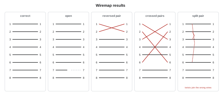
The split pair is the dangerous one. Its contact-to-contact map is perfect, so a simple continuity tester reports a pass. But the two conductors that should form a twisted pair are now in different pairs, so they are not twisted together. The pair has no balance, crosstalk between those pairs is very high, and the link fails at any significant data rate. Split pairs are usually made by an installer who wires the jack in straight colour order, white-orange, orange, white-green, green, and so on, instead of following the scheme, which puts the pair on 3-6 across two different pairs. A tester detects a split pair by measuring the crosstalk between the pairs, which is why better verification testers and every certification tester check for it.
Classifying a wiremap result
Testers present the wiremap as a diagram and a label. It helps to understand the logic, because the label alone can mislead, especially when there are two faults on one link. The code below takes the far-end contact each near-end contact reaches, plus a flag the tester sets when it measures high crosstalk between the pairs, and names the fault. It assumes both ends were meant to use the same scheme.
PAIRS = [(1, 2), (3, 6), (4, 5), (7, 8)]

def classify(m, split_flag=False):
    # m maps near-end contact to far-end contact; None for an open, a list for a short
    opens = [n for n in range(1, 9) if m.get(n) is None]
    shorts = [n for n in range(1, 9) if isinstance(m.get(n), list)]
    if opens:
        return "open on " + ", ".join(map(str, opens))
    if shorts:
        return "short between " + ", ".join(map(str, shorts))
    if all(m[n] == n for n in range(1, 9)):
        return "split pair (3-6 and 1-2 or 4-5)" if split_flag else "correct"
    faults = []
    for a, b in PAIRS:
        if m[a] == b and m[b] == a:
            faults.append(f"reversed pair {a}-{b}")
    if m[1] == 3 and m[2] == 6 and m[3] == 1 and m[6] == 2:
        faults.append("crossed pairs 1-2 and 3-6 (T568A to T568B)")
    return "; ".join(faults) if faults else "miswire"

good = {n: n for n in range(1, 9)}
tests = {
    "6A-E14": good,
    "6A-E15": {**good, 4: 5, 5: 4},
    "6A-E16": {**good, 1: 3, 2: 6, 3: 1, 6: 2},
    "6A-E17": {**good, 7: None},
    "6A-E18": good,
    "6A-E19": {**good, 2: [2, 3], 3: [2, 3]},
}
for link, m in tests.items():
print(link, classify(m, split_flag=(link == "6A-E18")))6A-E14 correct 6A-E15 reversed pair 4-5 6A-E16 crossed pairs 1-2 and 3-6 (T568A to T568B) 6A-E17 open on 7 6A-E18 split pair (3-6 and 1-2 or 4-5) 6A-E19 short between 2, 3
Each label points to its cause. The reversed pair on 6A-E15 is the blue pair's two conductors swapped in one jack. The crossed pairs on 6A-E16 mean one end is T568B. The open on 6A-E17 is one brown conductor not seated. The split pair on 6A-E18 passes contact by contact and is caught only by the crosstalk flag. The short on 6A-E19, between contacts 2 and 3, points to a nicked conductor or a stray strand at a termination. All six are offices on panel E, terminated by the same crew on the same afternoon, which tells Maya to have that crew's next ten checked as well.
Length and nominal velocity of propagation
Most verification and all certification testers report length. They do it by timing a pulse: the tester sends a signal down a pair and measures the time for its reflection to return from the open far end, or for it to reach the remote unit. The time becomes a length through the cable's nominal velocity of propagation, or NVP, the speed of the signal in the cable as a fraction of the speed of light. NVP for Category 6A cable is usually about 0.65 to 0.72, and it is printed on the cable's data sheet.
Here L is the length, c is the speed of light, about 3 × 10⁸ m/s, and t is the round-trip time of the reflection, halved because the signal travels out and back. The tester must be set to the cable's NVP; with the wrong NVP, every length is wrong by the same proportion. The four pairs of one cable also report slightly different lengths, because each has a different twist rate and so a different amount of conductor per metre of cable. That difference shows up as delay skew, the spread in arrival times between pairs, which lesson 10 covers as a certification parameter.
# Length of each pair from the reflection time, and the effect of a wrong NVP
c = 299_792_458                     # speed of light, m/s
NVP_CABLE = 0.68                    # from the data sheet
NVP_SET = 0.72                      # what the tester was left set to
times_ns = {"1-2": 640, "3-6": 632, "4-5": 627, "7-8": 636}   # round-trip times
for pair, t in times_ns.items():
    true = NVP_CABLE * c * t * 1e-9 / 2
    shown = NVP_SET * c * t * 1e-9 / 2
    print(f"pair {pair}: {true:5.1f} m actual, tester shows {shown:5.1f} m")
spread = (max(times_ns.values()) - min(times_ns.values())) / 2
print(f"one-way delay skew between pairs: {spread:.0f} ns")pair 1-2: 65.2 m actual, tester shows 69.1 m pair 3-6: 64.4 m actual, tester shows 68.2 m pair 4-5: 63.9 m actual, tester shows 67.7 m pair 7-8: 64.8 m actual, tester shows 68.6 m one-way delay skew between pairs: 6 ns
The link is about 64 m (210 ft) long, but a tester left at an NVP of 0.72 reports nearly 4 m (12 ft) more on every pair. On a link near the 90 m limit, that error could turn a pass into a reported failure. The pairs also differ by a little over a metre, which is normal. Maya's habit is to check the NVP setting on the tester at the start of every day and whenever the cable type changes, for example between the horizontal Category 6A and the backbone 25-pair cable.
Toning and tracing
Verification also includes finding cables. A tone generator connected to a cable at one end puts an audible signal on it, and an inductive probe held near the bundle at the other end finds the cable by its sound. Many verification testers have numbered remote identifiers: a set of small plugs, each with its own number, that are plugged into a group of outlets so that the tester at the panel identifies which outlet each port reaches. Maya uses a set of twelve remotes to confirm each pod's outlet-to-port mapping before the permanent labels are applied, which catches any cable whose pull label was lost or swapped.
When verification is enough
Some cabling does not need certification. The 25-pair backbone in rack 3 carries telephone and alarm circuits at low frequencies, and its acceptance test is a wiremap and continuity test on every pair, with a record of the results. Building systems wiring for controls is often verified rather than certified, depending on the specification. And on service calls in existing buildings, verification and qualification tests are often what the owner wants: does this link work, and will it carry this speed. But for new horizontal cabling under a warranty, verification is a tool for the installer, not an acceptance test.
Worked problem
Two faults on one link
A link at the Hartwell warehouse shows on a verification tester as near-end contacts 1, 2, 3, 6 reaching 3, 6, 1, 2 at the far end, but contact 2 is reported open. How should the result be read?
Show solution
- The pattern 1-2 to 3-6 means the ends are wired to different schemes, a crossed pair.
- In addition, contact 2's conductor is open, which the tester reports first, hiding the cross.
- Fixing only the open would leave the crossed pairs; fixing only the scheme would leave the open.
- Maya re-terminates the far-end jack to the specified scheme with a fresh cable end, which clears both faults.
Answer: There were two faults: an open and a scheme mismatch. Read the map, not only the label.
Verification on existing cabling
Cobalt Line's service crews spend much of their time in buildings they did not cable. There, verification is often the first step: a tester and a set of numbered remotes identify which outlets reach which ports, and a wiremap shows whether the old cabling is wired consistently. The records in older buildings are often wrong or missing, and the remotes are the fastest way to rebuild them. Qualification testing then answers the owner's real question, whether a given link will carry the speed they need, without the cost of full certification.
Two habits help on existing cabling. First, always confirm that nothing is powered on the link before connecting a tester; most testers tolerate PoE, but some older ones do not, and a telephone line on a mislabelled port can carry ringing voltage. Second, record the results as you go, against both the old labels and the new identifiers, so the work leaves the building's records better than it found them.
Common mistakes
MistakeAccepting a continuity tester's pass as proof of correct wiring.
InsteadUse a tester that detects split pairs; continuity alone misses them.
MistakeWiring a jack in straight colour order.
InsteadFollow the T568A or T568B order, which keeps the pair on 3-6 together.
MistakeLeaving the tester's NVP at whatever it was last set to.
InsteadSet the NVP for the cable being tested.
MistakeTesting only after the ceiling is closed.
InsteadVerify early terminations and doubtful links during the work.
MistakeReading only the fault label when there are two faults.
InsteadRead the full map.
Summary and key terms
- Testing has three tiers: verification of wiring, qualification for applications and certification against standard limits.
- A wiremap checks that every conductor reaches the right far-end contact and nothing else.
- Wiremap faults are opens, shorts, reversed pairs, crossed pairs, split pairs and miswires.
- Split pairs pass a continuity test and are found only by measuring crosstalk.
- Testers calculate length from the reflection time and the cable's NVP, which must be set correctly.
- Pairs differ slightly in length because of their twist rates, producing delay skew.
- Verification is the installer's everyday tool; new horizontal cabling under warranty needs certification.
- Verification
- Testing that a link is wired correctly, conductor by conductor.
- Qualification
- Testing whether an existing link can support a particular network application.
- Certification
- Swept-frequency testing of a link against the limits of its category in the standard.
- Wiremap
- A test showing which far-end contact each near-end conductor reaches.
- Split pair
- A fault in which the conductors of two pairs are mixed while the contacts match end to end.
- Nominal velocity of propagation (NVP)
- The speed of a signal in a cable as a fraction of the speed of light.
- Tone generator
- A device that puts an audible signal on a cable so it can be traced with a probe.
Practice problems
Work each problem on paper first, then reveal the answer to check.
A tester set to NVP 0.70 shows 70 m on a cable whose NVP is 0.66. What is the actual length?
Show answer
70 × 0.66 / 0.70 = 66 m.
Why does a split pair pass a simple continuity test?
Show answer
Each contact connects to the matching far-end contact; only the pairing is wrong.
What wiremap result does a link with T568A at one end and T568B at the other give?
Show answer
Crossed pairs between 1-2 and 3-6.
Which tier of tester is required for a manufacturer's system warranty?
Show answer
A certification tester.
Lesson quiz · 5 questions
Score 60% or more to complete this lesson.
Create a free account to save your progress, take quizzes and earn a certificate.