
LVT-130 · Lesson 2 of 12 · 19 min
Pathway prep and supporting cable
Most of a horizontal cable's life is spent lying still in a pathway above a ceiling. If the pathway is right, the cable will perform for decades; if it sags, kinks, crosses a light fixture or rests on a sprinkler pipe, the damage may not show in the first test but can appear years later as an intermittent fault that nobody can find. LVT-120 covered how pathways are designed under TIA-569. This lesson is about the installer's side: checking that the pathway is ready, installing the supports the designer specified, and leaving a route that a cable can be pulled through without harm.
Walking the route before the pull
Before the first pull in each zone, Maya walks the route with the drawings, a laser measure and a flashlight. She is checking four things. First, is the pathway there and complete: tray joined and bonded, J-hooks hung, sleeves through every rated wall, boxes and conduits in each wall cavity? Second, is it where the drawing put it, or has another trade moved it? Third, is it clear of things cable must not touch? Fourth, is the actual length of the route close to the takeoff, so that no cable will be pulled over the 90 m limit?
On the sixth floor, the walk finds two problems. In zone Z2 the duct installer has run a large supply duct through the space where the J-hook route was drawn, so the hooks have been hung below the duct, only a few centimetres above the ceiling grid wires. In the corridor south of the core, the tray ring passes directly under a row of fluorescent fixtures being replaced with LED panels, whose drivers will sit right beside the tray. Maya photographs both and Dev raises them at the coordination meeting. The J-hooks are moved to a new route beside the duct, and the electrical contractor agrees to mount the drivers on the far side of the fixtures.
Measuring the route is just as important. Maya measures the longest route in each zone from the rack position in room 6A, along the tray and hooks, down to the farthest outlet. The longest on the floor, to a training room outlet in the northeast corner, comes to about 67 m (220 ft) including a 3 m (10 ft) service loop in the room, which matches Sanjay's estimate and leaves a comfortable margin under the 90 m permanent link limit.
What cable must stay away from
Communication cable must be kept away from sources of physical damage and electrical noise, and away from building systems it could interfere with. The electrical code sets some separations as rules, and the cabling standards and manufacturers add recommendations. LVT-330 covers the code rules in detail; the installer's practical checklist on a commercial ceiling looks like this.
- Power wiring and equipment: no communication cable in the same raceway, enclosure or tray compartment as power unless a barrier is used, and practical separation from motors, transformers, ballasts and LED drivers, which are strong noise sources.
- Light fixtures: cables must not rest on fixtures, which are hot and are removed for service.
- Sprinkler pipes, ducts and other mechanical services: cables may not be supported by them or tied to them; they need their own supports from the structure.
- Ceiling grid and its wires: cable may not lie on the ceiling tiles or be supported by the grid wires, which carry the ceiling and are not rated for added load.
- Seismic bracing and fire-rated assemblies: cable must not pass through bracing or interfere with it, and any penetration of a rated wall or floor needs an approved firestop system.
The ceiling-wire rule has a code basis as well as a practical one: the electrical code requires cables to be supported by the building structure, not by the ceiling grid, except where the grid's support wires are installed specifically as additional supports for that purpose. Cobalt Line's specifications do not allow that exception, so every hook on the sixth floor hangs from its own rod, clip or beam clamp.
Open-ceiling supports: J-hooks and their spacing
Most horizontal cable on a commercial floor is not in conduit or tray but in what the standards call non-continuous support: J-hooks, bridle rings or saddles hung from the structure at intervals. A J-hook is a wide, smooth, curved support, usually with a flared lip and a latch, designed so that a bundle of cable rests on a surface with a radius larger than the cable's minimum bend radius. Bridle rings, which are narrow wire loops, concentrate the weight of the bundle on a small contact area and are generally limited to small numbers of cables and short drops.
The standards and manufacturers set two numbers for J-hooks. The spacing between supports must not exceed 1.5 m (5 ft), and the sag of the bundle between supports should be no more than about 300 mm (12 in). Closer spacing reduces sag and the weight on each hook. Many manufacturers also recommend that the spacing be slightly varied rather than perfectly regular, about 1.2 to 1.5 m (4 to 5 ft), because evenly repeated sag points on a very long run have been linked to small periodic effects on return loss. Dev's crews hang hooks at varied spacing as a matter of habit.
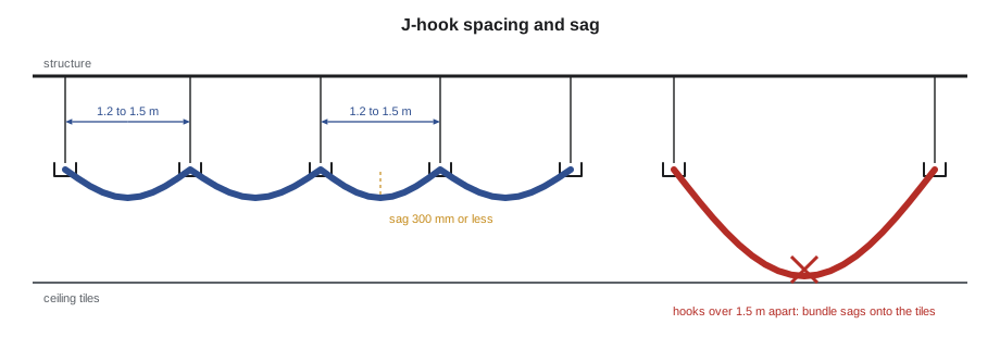
Each hook also has a capacity, the number of cables it may hold, which the manufacturer lists by hook size and cable diameter. A rough check from first principles uses the hook's cross-section, the cable's diameter and a fill factor that allows for the round cables not packing perfectly and for room to add cables later. The code below checks a 38 m (125 ft) route through zone Z2 with two hook sizes.
import math
OD = 7.4            # cable outside diameter, mm
W = 0.062              # cable weight per m of length
route = 38.0          # length of the J-hook route, m
MAX_SPAN = 1.5      # maximum spacing between supports, m
hooks = {"50 mm hook": 50, "75 mm hook": 75}
FILL = 0.5           # usable fraction of the hook's cross-section
cable_area = math.pi * (OD / 2) ** 2
n_supports = math.ceil(route / MAX_SPAN) + 1
print(f"supports needed for {route} m at {MAX_SPAN} m spacing: {n_supports}")
for name, d in hooks.items():
    area = math.pi * (d / 2) ** 2 * FILL
    n = int(area // cable_area)
    load = n * W * MAX_SPAN * 9.81       # newtons
print(f"{name}: about {n} cables, load per hook {load:.0f} N")supports needed for 38.0 m at 1.5 m spacing: 27 50 mm hook: about 22 cables, load per hook 20 N 75 mm hook: about 51 cables, load per hook 47 N
The route needs about 27 supports. A small hook holds a little over 20 Category 6A cables and a large one about 50, at loads of 20 to 47 N (5 to 11 lbf) per hook, well inside any listed rating. Zone Z2 has 24 cables plus four for access points, so Maya specifies the larger hooks, leaving room for growth. The capacity printed on the hook's packaging is the number to use on site; the calculation only shows why bigger bundles need bigger hooks.
Cable tray
The tray ring around the core of the sixth floor carries every cable on the floor at some point, so it gets the most attention. Wire-basket tray is the usual choice above office ceilings: light, easy to cut and bend in the field, and open so the cables can be seen. Before the pull, the tray must be complete and supported at the manufacturer's spacing, its sections joined with the correct splice hardware, its cut ends filed or capped so they cannot nick a jacket, and drop-outs or waterfall fittings installed wherever cables leave the tray, so they do not bend over a sharp wire edge.
Tray must also be bonded where the specification or the code requires it, as LVT-330 covers, and it must have room. LVT-120's design rule was an initial fill of about 25 percent, leaving space for future cables. On the sixth floor the corridor tray is 300 mm (12 in) wide and 100 mm (4 in) deep; near room 6A, where all eight zones converge, it widens to 450 mm (18 in).
Sleeves, conduit and pull strings
Where cable passes through a wall, it goes through a sleeve, a short length of conduit set in the wall, or a listed pathway device that includes its own firestop. Sleeves must be reamed and bushed so the cable does not drag over a sharp edge, and they must be sized so that the cables fill no more than the design allows. Through fire-rated walls, the sleeve and the cables are sealed with the specific listed firestop system shown in the submittals, after the pull, by whoever the specification makes responsible. Maya's crews never leave an open penetration at the end of a shift.
Conduit to individual outlets, usually from an accessible ceiling space down inside a wall to the outlet box, must have a pull string, be reamed and bushed, and have no more than two 90-degree bends between pull points. Conduits stubbed up into the ceiling should end with a bushing and be pointed toward the J-hook route, so cables enter without a sharp bend. Every conduit the crew uses gets a new pull string left in it for the next person.
Outlet boxes, zone boxes and access point locations
Outlet boxes for Category 6A should be deep enough to hold the cable's bend radius and the back of the jack. A shallow single-gang box forces the cable into a tight bend right behind the jack, which is exactly where performance is most sensitive. Many specifications call for double-gang, deep boxes with single-gang mud rings, and Sanjay's specification for the sixth floor does. The boxes are installed by the electrical contractor, so Maya checks a sample before the walls are boarded.
The eight zone boxes are ceiling enclosures that act as consolidation points, as LVT-120 described. Each is hung from the structure, accessible through a ceiling tile and at least 15 m (49 ft) of cable from room 6A. The access point and camera locations get a box or bracket above the ceiling, with a service loop of cable stored neatly, so the device can be relocated slightly when the wireless survey is checked after occupancy.
| Item checked | Acceptable | Not acceptable |
|---|---|---|
| J-hook spacing | 1.2 to 1.5 m (4 to 5 ft), varied | Over 1.5 m (5 ft) or hooks skipped at a duct |
| Bundle sag | About 300 mm (12 in) or less | Cables touching tiles or grid |
| Support from | Structure, by rod, clip or beam clamp | Ceiling wires, pipes or ducts |
| Tray | Joined, supported, ends filed or capped, drop-outs installed | Sharp cut ends, missing splice plates |
| Sleeves and conduit | Reamed and bushed, pull string in place | Sharp edges, no bushing, more than two 90s |
| Separation | Off fixtures, away from drivers and motors | Lying on lights or across power equipment |
| Outlet boxes | Deep enough for the bend radius | Shallow boxes forcing a tight bend |
Worked problem
A hook route that is too long
In zone Z7 the measured route from room 6A to the farthest office outlet is 79 m (259 ft), plus a 3 m (10 ft) room service loop and a 0.3 m (1 ft) outlet loop. Is this route acceptable, and what are the options?
Show solution
- Add the loops: 79 + 3 + 0.3 = 82.3 m (259 + 10 + 1 = 270 ft).
- The permanent link limit is 90 m (295 ft), so the route passes on length.
- But the ceiling there is under the roof, where LVT-120 found temperatures near 35 °C (95 °F) in summer, which reduces the allowable length to about 85 m (277 ft).
- The margin is only about 2 m (7 ft), too little to absorb any re-routing. Maya asks whether the hook route can cut across the open office instead of following the corridor.
Answer: The route passes, but with a small margin; a straighter route across the open office, about 8 m (26 ft) shorter, gives a safer result.
Common mistakes
MistakeHanging J-hooks from sprinkler pipes or ceiling wires.
InsteadSupport every hook from the structure.
MistakeSpacing hooks at whatever is convenient, sometimes 2.5 m (8 ft) apart.
InsteadKeep spacing at no more than 1.5 m (5 ft), slightly varied.
MistakeUsing narrow bridle rings for large bundles.
InsteadUse J-hooks sized for the bundle; rings only for a few cables on short drops.
MistakePulling over raw cut tray wire.
InsteadFile or cap cut ends and fit drop-out fittings.
MistakeLeaving a penetration open overnight.
InsteadSeal or temporarily close every penetration at the end of the shift, with the listed system as soon as the pull is complete.
Summary and key terms
- The pathway is walked and measured before each pull, and problems go to the coordination meeting.
- Cable stays off fixtures, pipes, ducts, ceiling tiles and grid wires, and away from noisy electrical equipment.
- Open-ceiling supports are J-hooks from the structure at no more than 1.5 m (5 ft), varied, with sag of about 300 mm (12 in) or less.
- Each support has a listed capacity; bigger bundles need bigger hooks.
- Tray must be complete, supported, filed, fitted with drop-outs and bonded where required.
- Sleeves and conduit are reamed and bushed, have pull strings, and are firestopped with the listed system.
- Deep outlet boxes, accessible zone boxes and service loops at devices protect bend radius and allow future moves.
- Non-continuous support
- Supports such as J-hooks placed at intervals, rather than a continuous tray or conduit.
- J-hook
- A wide, curved cable support hung from the structure, sized for a bundle of cables.
- Bridle ring
- A narrow wire loop support, suitable only for a few cables.
- Sag
- The droop of a bundle between supports.
- Drop-out fitting
- A curved fitting where cable leaves a tray, protecting its bend radius.
- Sleeve
- A short length of conduit through a wall or floor for cables to pass.
Practice problems
Work each problem on paper first, then reveal the answer to check.
A route is 45 m long with supports at no more than 1.5 m. How many supports are needed?
Show answer
45 / 1.5 = 30 spans, so 31 supports.
Twenty cables weighing 0.062 kg/m hang on hooks 1.5 m apart. About what load is on each hook?
Show answer
20 × 0.062 × 1.5 × 9.81 ≈ 18 N.
Why should cables not be supported by ceiling grid wires?
Show answer
The wires carry the ceiling, are not rated for the added load, and the code requires support from the structure.
What is wrong with a shallow outlet box behind a Category 6A jack?
Show answer
It forces a tight bend directly behind the jack, where performance is most sensitive.
Lesson quiz · 5 questions
Score 60% or more to complete this lesson.
Create a free account to save your progress, take quizzes and earn a certificate.