
ENGG-130 · Lesson 12 of 12 · 30 min
Case studies and design project
Statics is rarely used one topic at a time. Checking even a simple structure means estimating loads, replacing distributed loads by resultants, drawing free-body diagrams, solving for reactions and internal forces, locating centres of gravity, checking for sliding and tipping, and using section properties to see whether a member is strong enough. This final lesson works through two complete case studies, a roadside sign structure and the lifting of a precast concrete wall panel, that draw on every lesson of the course. It then sets out a design project in which you analyze a structure or machine of your own choosing, and closes with a look at where statics leads.
A general procedure
Experienced engineers approach a statics problem in the same order every time:
- Understand the structure and how it will be used. Sketch it, identify the supports and the load path, and list what could go wrong: sliding, tipping, a member overstressed, a connection failing.
- Establish the loads. Use codes and standards for live, snow and wind loads (Lesson 7), and the weights of materials for dead loads. State the load case being considered.
- Idealize the structure. Choose supports (pins, rollers, fixed ends), decide which members are two-force members, and replace distributed loads by resultants where appropriate.
- Draw free-body diagrams. This step decides whether the rest is right (Lessons 2 and 4).
- Solve, using equilibrium for reactions and the methods of joints, sections and internal forces for members (Lessons 4, 5 and 8).
- Check: equilibrium in another direction, a second method, an order-of-magnitude estimate, signs and units, and whether the answer makes physical sense.
- Interpret: compare forces and stresses with capacities, and decide what to change.
Case study 1: a roadside sign structure
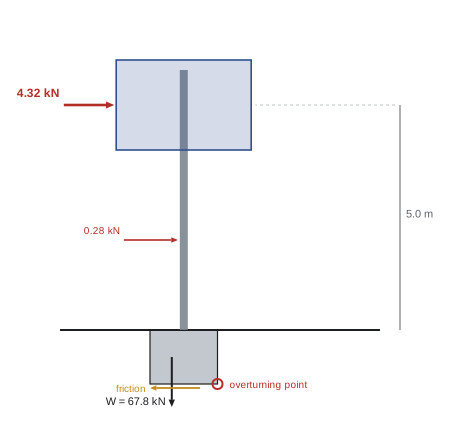
A highway agency needs a single-post sign, 3.0 m wide and 2.0 m high, with its centre 5.0 m above the ground, supported on a steel pipe post set into a square concrete block footing. The design wind pressure for the site, from the applicable code, gives a velocity pressure of 0.60 kPa. The engineer must check the post and the footing.
The load path is simple: wind on the sign face and on the post is carried by bending in the post to the footing, which must resist overturning and sliding by its weight and by friction on the soil. The wind force on the sign is its velocity pressure times a drag coefficient (about 1.2 for a flat sign) times its area, acting at the sign's centroid (Lessons 6 and 7). A round post has a lower coefficient, about 0.7.
import math

# Roadside sign on a single steel pipe post with a concrete block footing
q = 0.60                        # design wind velocity pressure, kPa
sign_w, sign_h, h_sign = 3.0, 2.0, 5.0       # sign size (m) and height of its middle above ground (m)
D, t, post_len = 0.1683, 0.0071, 4.0        # pipe outside diameter, wall, height below the sign (m)
F_sign = q * 1.2 * sign_w * sign_h          # drag coefficient 1.2 for a flat sign, kN
F_post = q * 0.7 * D * post_len             # drag coefficient 0.7 for a round post, kN
M_base = F_sign * h_sign + F_post * post_len / 2
print(f"Wind on sign {F_sign:.2f} kN, on post {F_post:.2f} kN, moment at ground {M_base:.1f} kN m")

ro, ri = D / 2 * 1000, (D / 2 - t) * 1000   # mm
I = math.pi * (ro ** 4 - ri ** 4) / 4
S = I / ro
print(f"Pipe: I = {I / 1e6:.2f} x 10^6 mm4, S = {S / 1e3:.0f} x 10^3 mm3, stress {M_base * 1e6 / S:.0f} MPa")

B, depth, gamma, W_sup = 1.5, 1.2, 24.0, 3.0  # square footing width, depth (m), concrete kN/m3, post and sign kN
W = gamma * B * B * depth + W_sup
M_over = F_sign * (h_sign + depth) + F_post * (post_len / 2 + depth)
M_resist = W * B / 2
mu = 0.5
print(f"Footing weight {W:.1f} kN: overturning FS {M_resist / M_over:.2f}, sliding FS {mu * W / (F_sign + F_post):.1f}")Wind on sign 4.32 kN, on post 0.28 kN, moment at ground 22.2 kN m Pipe: I = 11.70 x 10^6 mm4, S = 139 x 10^3 mm3, stress 159 MPa Footing weight 67.8 kN: overturning FS 1.84, sliding FS 7.4
The wind produces a moment of 22.2 kN·m at the base of the post, almost all from the sign. A standard 168 mm pipe with a 7.1 mm wall has a section modulus of 139 × 10³ mm³ (Lesson 11), giving a bending stress of 159 MPa, well below the yield strength of typical pipe steel (about 240 to 350 MPa); a design to the governing code would apply load and resistance factors and still find the post adequate. The 1.5 m square, 1.2 m deep footing weighs 68 kN with the sign and post. Taking moments about the leeward edge of its base, its weight resists overturning with a factor of safety of 1.84, and friction resists sliding with a factor of 7.4, both above the usual minimum of 1.5. In practice the soil around the footing adds passive resistance, a further margin.
Statics answers the strength and stability questions, but the engineer's work is not finished. Sign and light structures rarely fail by a single overload. More often they fail by fatigue: wind gusts and vortex shedding make the post vibrate millions of times, and cracks grow at the welds where the post joins its base plate, until a post falls without warning. Many highway agencies have had to inspect and replace sign, signal and light structures after such failures. Codes therefore require fatigue checks of the base connection, and the details used, such as thicker base plates, stiffeners and full-penetration welds, are chosen to keep fluctuating stresses low. Breakaway bases are also used near traffic lanes so that a vehicle striking the post is not stopped dead. The case shows that a statics calculation identifies the forces, and judgement about how a structure really behaves decides what else must be checked.
Case study 2: lifting a precast concrete panel
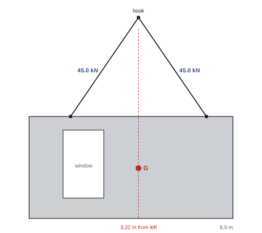
A precast concrete wall panel, 6.0 m long, 3.0 m high and 200 mm thick, has a window opening 1.2 m wide and 2.0 m high, whose lower-left corner is 1.0 m from the left end and 0.6 m above the bottom. The panel is to be lifted upright by a crane using two lifting inserts cast into its top edge and a pair of slings to a single hook. The erection engineer must decide where to place the inserts and find the sling forces. Concrete weighs 24 kN/m³.
Worked problem
Centre of gravity of the panel
Locate the panel's centre of gravity and find its weight.
Show solution
- Full panel: area 18.0 m², centroid (3.0, 1.5) m from the bottom-left corner.
- Window: area −2.4 m², centroid (1.0 + 0.6, 0.6 + 1.0) = (1.6, 1.6) m.
- \[\bar{x} = \frac{18.0(3.0) - 2.4(1.6)}{18.0 - 2.4} = \frac{54.0 - 3.84}{15.6} = 3.22 \text{ m} \qquad \bar{y} = \frac{18.0(1.5) - 2.4(1.6)}{15.6} = 1.48 \text{ m}\]
- Weight: \(15.6 \times 0.20 \times 24 = 74.9\) kN.
Answer: The centre of gravity is 3.22 m from the left end, 0.22 m right of the panel's centre because the window removes concrete from the left side, and 1.48 m above the bottom. The panel weighs about 75 kN (7.6 t).
Worked problem
Sling forces
The inserts are placed 2.0 m on each side of the centre of gravity, at x = 1.22 m and x = 5.22 m on the top edge, and the hook is 3.0 m directly above the centre of gravity's line. Find the tension in each sling.
Show solution
- Because the inserts are symmetric about the centre of gravity and the hook is above it, each sling carries half the weight vertically: 37.5 kN.
- Sling angle from horizontal: \(\tan^{-1}(3.0/2.0) = 56.3°\).
- Tension: \(T = 37.5/\sin 56.3° = 45.0\) kN. Horizontal component: \(45.0\cos 56.3° = 25.0\) kN, pulling the inserts toward each other.
Answer: Each sling carries 45.0 kN, 20 % more than half the panel's weight, because the slings are inclined (Lesson 2). The horizontal components, 25 kN each, compress the top of the panel between the inserts. Flatter slings would increase both: at 30° from horizontal, each sling would carry 75 kN, which is why rigging rules limit sling angles and why spreader beams are used for long panels.
If the inserts had been placed symmetrically about the panel's geometric centre instead (at x = 1.0 and 5.0 m), the hook would have to be above the midpoint, 0.22 m left of the centre of gravity, and the panel would rotate as it left the ground until its centre of gravity hung directly below the hook, tilting by several degrees and loading one sling more than the other. Panels that swing or tilt unexpectedly during lifting injure workers and damage the panel, so precast designers locate inserts from the centre of gravity, check the inserts' pull-out capacity (with large safety factors, since the concrete may be young), and check the panel itself for bending stresses during lifting, which can exceed those it will see in service. Lifting is often the most critical load case a precast element ever experiences.
Case study 3: a quick check of a footbridge truss
Statics is also used to check designs quickly. A pedestrian bridge is a Pratt truss 24 m long with six panels of 4 m and a depth of 3 m, carrying a design load that works out to 30 kN at each of the five interior bottom joints. The engineer wants the force in the bottom chord at midspan, the most heavily loaded tension member.
Worked problem
Method of sections
Find the force in the bottom chord member at midspan.
Show solution
- Reactions: total load 150 kN, so 75 kN at each support by symmetry.
- Cut through the middle panel and take moments about the top joint at midspan (12 m from the left support), where the other two cut members meet: \(75(12) - 30(8) - 30(4) - T(3) = 0\).
- \(T = (900 - 360)/3 = 180\) kN, tension.
- Check with the beam analogy: the midspan moment of an equivalent simple beam is 540 kN·m, and dividing by the depth gives 180 kN. ✓
Answer: 180 kN tension in the bottom chord, and by the same moment arm the top chord carries 180 kN compression. The top chord, being in compression, must be checked for buckling between panel points (Lesson 11), which usually makes it a heavier member than the bottom chord despite equal forces.
Design project
The course project asks you to analyze a real or realistic structure or machine from your surroundings, such as a balcony, a pedestrian bridge, a bicycle rack, a playground structure, a shelving unit, a crane or hoist, a sign, a retaining wall, a truss roof, or a piece of exercise equipment, and to recommend whether it is adequate or how it should be improved. Your report, about ten pages, should:
- Describe the structure with dimensioned sketches and photographs, and identify its load path and possible failure modes.
- Establish loads from a code or standard, or justify them from measurements and reasoning, and state the load cases.
- Draw complete free-body diagrams and find all support reactions.
- Find the forces in at least three members or the internal shear and moment diagrams of at least one member.
- Locate at least one centre of gravity and check at least one case of tipping, sliding or friction.
- Compute the section properties of a critical member and estimate its stress, comparing it with the material strength.
- Use a short Python script to automate at least one calculation and to explore how the result changes with a design variable, such as a span, depth or load.
- Check results by a second method, and discuss assumptions, uncertainties and what a full design would also need to consider, such as fatigue, connections, deflection or buckling.
Where statics leads
Statics is the foundation for most of the engineering courses that follow. Mechanics of materials uses the internal forces and section properties from Lessons 8 and 11 to find stresses, strains and deflections, and to design beams, shafts and columns. Structural analysis extends the methods of Lessons 4, 5 and 8 to statically indeterminate structures, where equilibrium alone is not enough and deformations must be considered. Dynamics, which is statics plus acceleration, treats moving bodies with the same free-body diagrams. Fluid mechanics builds on the hydrostatics of Lesson 7, and machine design on the friction, screws and belts of Lesson 10. In every case, the habits developed here, careful free-body diagrams, consistent units, checking by a second method and asking whether the answer makes sense, are what make the later analysis trustworthy.
Common mistakes
MistakeStarting calculations before identifying the load path and failure modes.
InsteadSketch the structure and list what could go wrong first.
MistakeChecking strength but not stability.
InsteadCheck sliding, overturning and buckling as well as stress.
MistakePlacing lifting points at the geometric centre of an unsymmetric object.
InsteadLocate them from the centre of gravity.
MistakeIgnoring sling angles.
InsteadInclined slings carry more than their share of the weight; limit the angle.
MistakeAssuming a statics check covers everything.
InsteadConsider fatigue, connections, deflection and construction loads too.
Summary and key terms
- Follow a consistent procedure: load path, loads, idealization, free-body diagrams, solution, checks, interpretation.
- A sign structure needs wind loads, bending stress in the post, and overturning and sliding checks of the footing.
- Real sign structures often fail by fatigue at base welds; statics identifies the forces, judgement identifies the checks.
- Precast lifting points must be placed about the centre of gravity, and sling angles limited.
- Method of sections and the beam analogy give quick checks of truss chord forces.
- The project applies every lesson to a real structure, with a Python script and checks.
- Statics leads to mechanics of materials, structural analysis, dynamics, fluids and machine design.
- Load path
- The route by which loads travel through a structure to the ground.
- Load case
- A specific combination of loads considered in a check.
- Idealization
- Representing a real structure by a simplified model of members and supports.
- Drag coefficient
- A factor relating wind pressure to force on a particular shape.
- Fatigue
- Cracking and failure under many repeated stress cycles below the static strength.
- Breakaway base
- A post base designed to release when struck by a vehicle.
- Lifting insert
- A cast-in anchor used to lift a precast element.
- Spreader beam
- A beam that keeps slings vertical when lifting long objects.
- Beam analogy
- Estimating truss chord forces as bending moment divided by truss depth.
- Statically indeterminate
- Having more unknowns than equilibrium equations can solve.
Practice problems
Work each problem on paper first, then reveal the answer to check.
If the sign's design wind pressure rose to 0.90 kPa, what would the base moment be?
Show answer
22.2 × 1.5 = 33.3 kN·m.
What bending stress would that cause in the same post?
Show answer
159 × 1.5 = 239 MPa.
Find the overturning factor of safety of the footing at 0.90 kPa.
Show answer
1.84/1.5 = 1.23, below 1.5; the footing must be enlarged.
Why do sign structures need fatigue checks?
Show answer
Wind causes millions of stress cycles that can crack welds at the base.
Without the window, where would the panel's centre of gravity be?
Show answer
At its centre, (3.0, 1.5) m.
With the hook 2.0 m above the inserts (still 2.0 m each side of G), find the sling tension.
Show answer
Angle 45°; T = 37.5/sin 45° = 53.0 kN.
What does a spreader beam do?
Show answer
It keeps the slings near vertical, reducing sling tension and compressive forces on the load.
In the truss case, find the bottom chord force in the end panel.
Show answer
Moments about the first top joint: 75 × 4/3 = 100 kN tension.
Why is the top chord often heavier than the bottom chord despite equal forces?
Show answer
It is in compression and must resist buckling.
Name three courses that build directly on statics.
Show answer
For example: mechanics of materials, structural analysis, dynamics, fluid mechanics, machine design.
Lesson quiz · 5 questions
Score 60% or more to complete this lesson.
Create a free account to save your progress, take quizzes and earn a certificate.