
ELE-490 · Lesson 6 of 12 · 22 min
Interconnection standards and grid codes
Every interconnection study starts by asking what the resource must be able to do. Twenty years ago the answer for distributed generation was mostly what it must not do: it must not regulate voltage, must not island and must disconnect quickly whenever the grid was disturbed. As distributed and inverter-based resources grew, that philosophy became dangerous, because thousands of small plants tripping at once during a transmission fault could turn a minor disturbance into a blackout. Modern standards reverse it: resources must stay connected through disturbances, support voltage and frequency, and still never energize a feeder that the utility has disconnected. This lesson surveys the standards that set those requirements and how Larchmont applies them to Birch Hill.
The distribution interconnection standard
In Canada the national standard is CSA C22.3 No. 9, Interconnection of distributed resources and electricity supply systems, whose current edition dates from 2020. It covers the technical requirements at the point of common coupling: voltage and frequency limits, synchronization, protection against islanding, power quality, grounding and the response to abnormal conditions. The 2020 edition takes an approach similar in purpose to IEEE 1547-2018, the corresponding standard in the United States, by addressing ride-through and grid-support functions. Inverters themselves are certified to CSA C22.2 No. 107.1, and many Canadian utilities also accept or reference IEEE 1547-2018 and UL 1741 testing. Each utility publishes its own technical interconnection requirements that apply these standards to its system, and Larchmont's are no exception.
IEEE 1547-2018 introduced a structure that many other documents, in both countries, now borrow. Resources are assigned to performance categories. For normal operation, Category A requires modest reactive power capability and is intended mainly for rotating machines; Category B requires more, about 44 % of the rated apparent power in either direction, and is the usual choice for inverters. For abnormal conditions, Categories I, II and III set progressively more demanding ride-through and trip requirements: Category I suits technologies with limited ride-through capability, Category II aligns broadly with bulk-system reliability expectations, and Category III, the most demanding, was developed for systems with very high DER penetration.
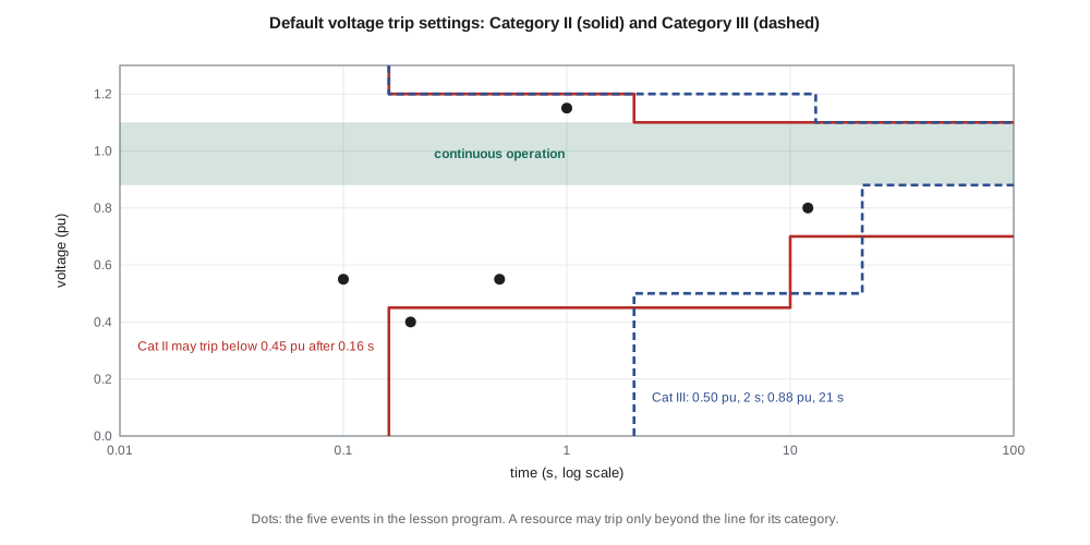
Ride-through and trip settings
Ride-through requirements define how long a resource must stay connected, and in what mode, while voltage or frequency is outside its normal range. Inside the continuous operating range, roughly 0.88 to 1.10 pu for voltage, the resource operates normally. Below it there are regions of mandatory operation, where the resource must keep delivering current, and regions of permissive operation or momentary cessation, where it may stop injecting current but must stay connected and resume quickly when voltage recovers. Only outside all of these regions may it trip.
Trip settings, often called clearing times, are the other side of the same boundary: they define how quickly the resource must disconnect for each band of abnormal voltage or frequency. IEEE 1547-2018 gives default values for each category and allows the utility to adjust them within ranges. The defaults are deliberately set beyond the ride-through regions, so a properly set resource will not trip for disturbances the bulk system expects it to survive. The program checks several events against the commonly published default settings for Categories II and III.
# Default trip (clearing) settings commonly published for IEEE 1547-2018 (pu of nominal, seconds).
# A DER must not trip earlier than these; utilities may adjust them within allowed ranges.
TRIP = {
    'Category II':  {'OV2': (1.20, 0.16), 'OV1': (1.10, 2.0), 'UV1': (0.70, 10.0), 'UV2': (0.45, 0.16)},
    'Category III': {'OV2': (1.20, 0.16), 'OV1': (1.10, 13.0), 'UV1': (0.88, 21.0), 'UV2': (0.50, 2.0)},
}
FREQ = {'OF2': (62.0, 0.16), 'OF1': (61.2, 300.0), 'UF1': (58.5, 300.0), 'UF2': (56.5, 0.16)}
def voltage_trip(cat, v, t):
    s = TRIP[cat]
    if v >= s['OV2'][0]: return t >= s['OV2'][1]
    if v > s['OV1'][0]: return t >= s['OV1'][1]
    if v < s['UV2'][0]: return t >= s['UV2'][1]
    if v < s['UV1'][0]: return t >= s['UV1'][1]
    return False
def freq_trip(f, t):
    if f >= FREQ['OF2'][0]: return t >= FREQ['OF2'][1]
    if f > FREQ['OF1'][0]: return t >= FREQ['OF1'][1]
    if f <= FREQ['UF2'][0]: return t >= FREQ['UF2'][1]
    if f < FREQ['UF1'][0]: return t >= FREQ['UF1'][1]
    return False
events = [('138 kV fault cleared in 6 cycles', 0.55, 0.10), ('slow-cleared 138 kV fault', 0.55, 0.50),
          ('deep sag at a nearby fault', 0.40, 0.20), ('long undervoltage after a line trip', 0.80, 12.0),
          ('overvoltage after load rejection', 1.15, 1.0)]
for name, v, t in events:
    r = [('trip' if voltage_trip(c, v, t) else 'ride through') for c in TRIP]
    print(f"{name:37s} {v:.2f} pu for {t:5.2f} s:  Cat II {r[0]:12s} Cat III {r[1]}")
for name, f, t in (('loss of a large unit', 59.3, 20), ('severe underfrequency', 57.8, 400), ('islanded overfrequency', 62.4, 0.2)):
print(f"{name:37s} {f:.1f} Hz for {t:5.1f} s: {'trip' if freq_trip(f, t) else 'ride through'}")138 kV fault cleared in 6 cycles 0.55 pu for 0.10 s: Cat II ride through Cat III ride through slow-cleared 138 kV fault 0.55 pu for 0.50 s: Cat II ride through Cat III ride through deep sag at a nearby fault 0.40 pu for 0.20 s: Cat II trip Cat III ride through long undervoltage after a line trip 0.80 pu for 12.00 s: Cat II ride through Cat III ride through overvoltage after load rejection 1.15 pu for 1.00 s: Cat II ride through Cat III ride through loss of a large unit 59.3 Hz for 20.0 s: ride through severe underfrequency 57.8 Hz for 400.0 s: trip islanded overfrequency 62.4 Hz for 0.2 s: trip
A fault on the 138 kV system that drops Lincoln Road's voltage to 0.55 pu for six cycles, as most transmission faults would, must not trip Birch Hill under either category. Even a slow-cleared fault lasting half a second is ridden through. A deeper sag to 0.40 pu lasting 0.2 s would allow a Category II resource to trip, but a Category III resource must stay connected. A long undervoltage at 0.80 pu after a line trip, or a 1.15 pu overvoltage for a second, are both ridden through. On frequency, a dip to 59.3 Hz for 20 seconds, the kind of event that follows the loss of a large generator, must be ridden through, while 57.8 Hz sustained for several minutes, or 62.4 Hz on an island, leads to a trip.
These results matter far beyond Birch Hill. If every distributed resource in a region tripped at 0.88 pu, as older settings sometimes required, a single transmission fault could disconnect hundreds of megawatts of solar across a wide area at the very moment the system most needed it. Analyses of events in several North American regions have documented exactly that kind of widespread loss, which is why ride-through is now required rather than merely permitted.
Grid-support functions
The second major change is that resources must actively support the grid. IEEE 1547-2018 requires Category B resources to be capable of several voltage regulation modes: constant power factor, constant reactive power, voltage–reactive power (volt-var) and active power–reactive power (watt-var). It also requires a voltage–active power (volt-watt) function that reduces real output when voltage is high, and frequency–droop response that reduces output when frequency rises above a deadband and, where the resource has headroom, increases it when frequency falls. The utility chooses which mode is active and sets its parameters; lessons 8 and 11 show how Larchmont chooses them for Birch Hill.
Interoperability is the third pillar. A modern DER must have a communication interface through which the utility can read its status and change its settings, using standard protocols such as IEEE 2030.5, DNP3 or SunSpec Modbus. This lets the utility, for example, switch a fleet of inverters from constant power factor to volt-var, or limit their output during an emergency, without sending crews to every site. Communication also raises cybersecurity questions, since an attacker who could change thousands of inverter settings at once could affect the bulk system; utilities therefore require authentication, encryption and limits on what remote commands can do, a defensive concern that grows with every connected device.
Worked problem
Reactive capability required by Category B
Birch Hill's solar inverters total 11 MVA. Category B requires reactive capability of about 44 % of rated apparent power in either direction at rated real power output. How much reactive power must the solar plant be able to supply or absorb, and can it do so at 10 MW?
Show solution
- \[Q_{\text{req}} = 0.44 \times 11\ \text{MVA} \approx 4.8\ \text{Mvar}\]
- At 10 MW and nominal voltage, lesson 3 found 4.6 Mvar available.
- The requirement is defined at the resource's rated active power; with 10 MW rated, the plant is just short at nominal voltage.
Answer: About 4.8 Mvar; Birch Hill's 4.6 Mvar at 10 MW is slightly short, so Leo notes that the developer must confirm the capability at the rated point or add margin.
Requirements at the transmission level
Large plants connected to the transmission system follow the transmission provider's requirements, which increasingly reference IEEE 2800-2022, the standard for inverter-based resources interconnecting with transmission and sub-transmission systems. In Canada, reliability standards developed by NERC become enforceable through provincial regulators and arrangements, and NERC's expanded registration of smaller inverter-based plants in the United States has prompted similar discussion in Canadian jurisdictions. For Birch Hill, a distribution-connected plant, these requirements matter indirectly: if enough distributed resources connect, their aggregate behaviour affects the bulk system and must appear in the transmission operator's models.
A key difference between the distribution and transmission documents is where the requirement applies. IEEE 1547 applies at the point of common coupling or point of DER connection, often a single facility on a feeder. IEEE 2800 applies at the point of measurement of a whole plant and assumes a plant controller coordinating many inverters. The two have been developed so that their ride-through concepts are broadly compatible, but their reactive power and fault-current requirements differ in detail.
Entering service and choosing settings
Standards also govern how a resource returns after a disturbance. Under the enter-service requirements of IEEE 1547-2018, a resource that has tripped must wait until voltage and frequency have been inside normal ranges for a set period, five minutes by default, and then ramp its output up gradually rather than stepping back to full power. If every inverter on a feeder reconnected at the same instant after an outage, the sudden return of several megawatts could overshoot voltage or confuse the restoration. The utility can adjust the delay and the ramp, and it can randomize reconnection across a fleet of small systems so that they do not all return together.
Choosing among the many adjustable settings is now an engineering task in its own right. A utility must decide which performance category it will require, which voltage-regulation mode is active by default, what trip settings it wants inside the permitted ranges and how quickly resources may ramp. Those choices should be consistent across a region, because the transmission operator models distributed resources in aggregate, and a utility whose settings differ sharply from its neighbours' complicates that model. Larchmont's planners coordinate their default settings with the transmission operator for exactly that reason.
Anti-islanding
An island forms when part of the utility system, disconnected from the rest by an opening breaker or recloser, continues to be energized by local generation. Unintentional islands are dangerous: crews may be working on lines they believe are dead, voltage and frequency drift outside limits, and reclosing onto an energized island out of phase can damage equipment. Interconnection standards therefore require that a resource detect an unintentional island and cease to energize it within a set time, two seconds under IEEE 1547-2018.
Inverters detect islands with passive methods, which watch for voltage, frequency or phase jumps, and active methods, which inject small perturbations and look for the larger response that appears when the grid's stiffness is gone. Certified inverters pass a standardized test with a matched resistive, inductive and capacitive load that makes the island hard to detect. Large plants, or feeders where many resources could balance the load, often need direct transfer trip, a communication signal from the utility's breaker that trips the plant, which Leo saw at the F3 solar plant during his protection term. Lesson 9 returns to how anti-islanding interacts with reclosing.
Leo summarizes the requirements for Birch Hill in a table for Marguerite: compliance with CSA C22.3 No. 9 and Larchmont's technical interconnection requirements; certified inverters; ride-through and trip settings agreed with the utility, aligned with Category II-type behaviour; voltage support in a mode to be chosen in the study; a 10 MW export limit enforced by the plant controller and backed up by a protective relay; direct transfer trip from the feeder breaker; and a communication link to Larchmont's control centre.
Common mistakes
MistakeSetting distributed resources to trip quickly for any voltage dip.
InsteadModern standards require ride-through so that a transmission fault does not trip large amounts of generation.
MistakeTreating momentary cessation as a trip.
InsteadUnder momentary cessation the resource stays connected and resumes when voltage recovers.
MistakeAssuming certification to the standard settles every requirement.
InsteadThe utility still chooses settings, modes and limits for its own system.
MistakeAssuming inverter anti-islanding is enough on every feeder.
InsteadLarge plants or high penetration may need direct transfer trip.
Summary and key terms
- Modern interconnection standards require resources to ride through disturbances and support the grid, while preventing unintentional islands.
- IEEE 1547-2018 defines normal performance Categories A and B and abnormal performance Categories I, II and III.
- Ride-through regions define where resources must keep operating; default trip settings lie beyond them.
- Grid-support functions include constant power factor, constant reactive power, volt-var, watt-var, volt-watt and frequency-droop response.
- Interoperability requires a standard communication interface and raises cybersecurity requirements.
- Transmission-connected IBR follow requirements based increasingly on IEEE 2800-2022.
- Unintentional islands must be detected and de-energized within about two seconds; large plants may need transfer trip.
- Ride-through
- The requirement to stay connected and operate in a specified mode during abnormal voltage or frequency.
- Momentary cessation
- Temporarily stopping current injection while remaining connected.
- Clearing time
- The maximum time within which a resource must disconnect for a given abnormal condition.
- Performance category
- A class of required capability defined in IEEE 1547-2018.
- Interoperability
- The ability of a resource to exchange information and accept settings through standard interfaces.
- Unintentional island
- A part of the system that remains energized by local generation after being disconnected from the utility.
- Direct transfer trip
- A communication-based trip of a generator from a utility breaker opening.
Practice problems
Work each problem on paper first, then reveal the answer to check.
A fault drops voltage to 0.60 pu for 0.15 s. May a Category II resource trip?
Show answer
No; it must ride through.
What is the default undervoltage trip threshold and time for UV1 in Category III?
Show answer
0.88 pu for 21 s.
Why did older settings that tripped DER at 0.88 pu create a risk for the bulk system?
Show answer
A single transmission fault could trip large amounts of DER at once.
Name three reactive power control modes required of Category B resources.
Show answer
Constant power factor, constant reactive power and volt-var (also watt-var).
Within what time must a DER cease to energize an unintentional island under IEEE 1547-2018?
Show answer
Two seconds.
Why does remote access to inverter settings need strong security?
Show answer
Changing many inverters' settings at once could disturb the bulk system.
Lesson quiz · 5 questions
Score 60% or more to complete this lesson.
Create a free account to save your progress, take quizzes and earn a certificate.