
ELE-490 · Lesson 10 of 12 · 20 min
Power quality and harmonics
Power quality complaints are the integration problems customers notice first. A farm near Birch Hill's site already has a variable-speed irrigation pump and a grain dryer, and the farmer has asked Larchmont whether a 10 MW plant next door will make his lights flicker or his drives misbehave. Leo's job in this lesson is to answer that kind of question with numbers: to check Birch Hill's harmonic emissions against the limits, to look for resonance between the plant and the feeder's capacitance, and to estimate the voltage steps and fluctuations that the plant could cause.
What power quality covers
Power quality is a broad term for the ways the voltage at a customer's service can depart from a perfect sinusoid of constant magnitude and frequency. The main phenomena are steady-state voltage magnitude, covered in lesson 8; harmonics, distortion of the waveform by currents at integer multiples of the fundamental frequency; interharmonics at non-integer frequencies; voltage fluctuations and flicker, repeated changes in magnitude that make lights visibly flicker; rapid voltage changes, single steps; voltage unbalance between phases; DC injection; and transients from switching and lightning. Inverter-based resources can affect most of them, mostly modestly, but the large size of utility plants means the effects must be checked.
Harmonics from inverters
An inverter synthesizes its AC output by switching DC at a high frequency, typically several kilohertz, and filtering the result. The switching itself produces components near the switching frequency and its multiples, which the output filter attenuates heavily. Imperfections in the control and the filter, dead time in the switches and distortion already present in the grid voltage produce smaller low-order harmonics, typically the 5th, 7th, 11th and 13th. Modern grid-tied inverters keep total current distortion at rated output to a few percent, far lower than the six-pulse rectifiers in older drives, whose 5th harmonic alone could exceed 20 % of fundamental.
Harmonic currents matter because they flow through the system impedance and distort the voltage that every other customer sees. Distorted voltage overheats transformers and motors, causes capacitor banks to draw excess current, disturbs electronic equipment and interferes with communication circuits. Utilities therefore limit both the harmonic current a customer may inject and the voltage distortion on the system.
In Canada, utilities typically base their harmonic limits either on IEEE 519 or on the emission-allocation approach of the IEC 61000 series, together with the harmonic requirements of CSA C22.3 No. 9 for distributed resources. Larchmont's technical interconnection requirements reference IEEE 519 for customer installations and apply an inverter current-distortion limit consistent with the distributed-resource standards: about 5 % total rated-current distortion at the point of connection.
IEEE 519 limits voltage distortion according to the bus voltage: for systems above 1 kV and up to 69 kV, individual harmonics may not exceed 3 % of the fundamental voltage and total harmonic distortion (THD) may not exceed 5 %. Current limits depend on the ratio of the available short-circuit current to the customer's maximum demand current, because a strong system tolerates more current distortion before its voltage is affected. Power generation facilities, however, are held to the most restrictive row, the one for ratios below 20, whatever their actual ratio: 4 % for harmonics below the 11th, falling to 0.3 % above the 35th, with a total demand distortion (TDD) of 5 %. Even harmonics up to the 6th are limited to half the corresponding odd-harmonic values.
import math
# 1. Harmonic current at Birch Hill's POI from the inverter test report (percent of rated current)
I_RATED = 10e6/(math.sqrt(3)*24.94e3)              # 231 A
spec = {5: 1.6, 7: 1.1, 11: 0.9, 13: 0.7, 17: 0.4, 19: 0.35, 23: 0.25, 25: 0.2, 29: 0.15, 35: 0.1, 2: 0.3, 4: 0.2}
tdd = math.sqrt(sum(v**2 for v in spec.values()))
print(f"total demand distortion {tdd:.2f} % of rated current ({tdd/100*I_RATED:.1f} A)")
limits = [(2, 11, 4.0), (11, 17, 2.0), (17, 23, 1.5), (23, 35, 0.6), (35, 51, 0.3)]   # IEEE 519 row Isc/IL < 20
for h, v in sorted(spec.items()):
    lim = next(l for a, b, l in limits if a <= h < b)
    if h % 2 == 0 and h <= 6: lim *= 0.5                                                 # even harmonics h <= 6
    print(f"  h = {h:2d}: {v:4.2f} % (limit {lim:4.2f} %) {'OK' if v <= lim else 'EXCEEDS'}")
print(f"TDD {tdd:.2f} % against 5.0 % -> {'OK' if tdd <= 5 else 'EXCEEDS'}")
# 2. Parallel resonance between the 25 kV source and a capacitor bank
Ssc = math.sqrt(3)*24.94*5.62                       # MVA at the 25 kV bus
for qc in (1.2, 3.6, 6.0):                          # Mvar of capacitance (bank plus plant cables)
    print(f"capacitance {qc:3.1f} Mvar: parallel resonance near harmonic {math.sqrt(Ssc/qc):4.1f}")
# 3. Rapid voltage change at the 11 km POI if Birch Hill trips from full output
R, X, V = 0.11*11, 0.40*11, 24.94
for mode, q in (('unity power factor', 0.0), ('volt-var, absorbing 0.83 Mvar', -0.83)):
    dv = (10.0*R + q*X)/V**2*100
    print(f"trip from 10 MW, {mode}: voltage step {dv:.2f} %")
print(f"cloud front: 70 % output drop over 30 s at unity -> {0.7*10*R/V**2*100:.2f} % spread over 30 s")total demand distortion 2.37 % of rated current (5.5 A) h = 2: 0.30 % (limit 2.00 %) OK h = 4: 0.20 % (limit 2.00 %) OK h = 5: 1.60 % (limit 4.00 %) OK h = 7: 1.10 % (limit 4.00 %) OK h = 11: 0.90 % (limit 2.00 %) OK h = 13: 0.70 % (limit 2.00 %) OK h = 17: 0.40 % (limit 1.50 %) OK h = 19: 0.35 % (limit 1.50 %) OK h = 23: 0.25 % (limit 0.60 %) OK h = 25: 0.20 % (limit 0.60 %) OK h = 29: 0.15 % (limit 0.60 %) OK h = 35: 0.10 % (limit 0.30 %) OK TDD 2.37 % against 5.0 % -> OK capacitance 1.2 Mvar: parallel resonance near harmonic 14.2 capacitance 3.6 Mvar: parallel resonance near harmonic 8.2 capacitance 6.0 Mvar: parallel resonance near harmonic 6.4 trip from 10 MW, unity power factor: voltage step 1.95 % trip from 10 MW, volt-var, absorbing 0.83 Mvar: voltage step 1.36 % cloud front: 70 % output drop over 30 s at unity -> 1.36 % spread over 30 s
Birch Hill's inverter test report gives a harmonic spectrum at rated output, and the program checks each component against the limits. The largest, the 5th harmonic at 1.6 % of rated current, is well inside its 4 % limit, and the total demand distortion is 2.37 %, against a limit of 5 %. The plant passes comfortably. Leo notes one caveat from the test report: the measurements were made on a single inverter on a stiff test grid. The utility's requirement is at the point of interconnection, with four inverters in parallel and the plant's collector cables, so the developer must also show that the plant as a whole does not create a resonance that amplifies any component.
Resonance
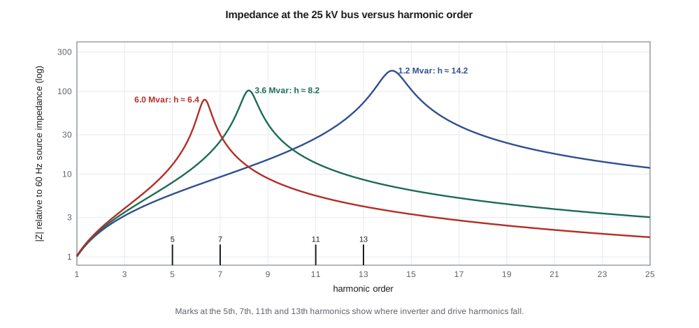
Capacitance and inductance in a power system form resonant circuits. At the 25 kV bus, the inductive source impedance in parallel with capacitor banks and cable capacitance forms a parallel resonance whose frequency, expressed as a harmonic order, is approximately h ≈ √(Ssc/Qc), where Ssc is the bus short-circuit capacity and Qc the capacitive reactive power. Near that frequency, the impedance seen by harmonic currents becomes very high, and even small injected currents produce large voltage distortion. The program shows that Lincoln Road's 1.2 Mvar capacitor bank resonates near the 14th harmonic, while 3.6 Mvar would move it to about the 8th and 6.0 Mvar to about the 6th, close to the 5th and 7th harmonics that inverters and drives produce.
Birch Hill's underground collector cables add capacitance, and if the developer later added a capacitor bank to extend reactive capability, the combined capacitance could move a resonance close to a characteristic harmonic. Inverters add another complication: their own control and filter can interact with the grid impedance, producing resonances or instabilities in the range of a few hundred hertz to a few kilohertz that do not appear in a simple harmonic study. Detailed frequency scans of the plant's impedance, provided by the manufacturer, are increasingly required for large plants on weaker parts of the grid.
Worked problem
Will a new capacitor bank create a problem?
Larchmont considers adding a 4.8 Mvar bank at Lincoln Road's 25 kV bus, where the short-circuit capacity is about 243 MVA. Estimate the parallel resonant harmonic and say whether it is a concern.
Show solution
- \[h \approx \sqrt{\dfrac{S_{sc}}{Q_c}} = \sqrt{\dfrac{243}{4.8}} \approx 7.1\]
- The resonance falls almost exactly on the 7th harmonic, a characteristic harmonic of inverters and drives.
Answer: About the 7th harmonic, which is a concern; the bank should be detuned with a series reactor or split into smaller steps.
Flicker and rapid voltage change
Voltage fluctuations become flicker when they modulate the light output of lamps at rates the eye can see, most noticeably around 8 to 10 changes per second. Flicker is measured with a standardized flickermeter that produces a short-term severity index, Pst, over 10 minutes and a long-term index, Plt, over 2 hours. A Pst of 1.0 corresponds roughly to the threshold at which half of observers find the flicker irritating. Utilities set planning levels below that, often around 0.8 to 1.0 for Pst on medium-voltage systems, and allocate a share to each large customer.
Solar plants cause slow fluctuations rather than rapid ones. A passing cloud reduces irradiance over tens of seconds across a large plant, and the inverters' output follows smoothly, so the voltage change at the POI is spread out in time and rarely produces measurable flicker. The program shows that a 70 % output drop as a cloud front crosses Birch Hill would change voltage by about 1.4 % over half a minute. Many interconnection requirements also limit plant ramp rates, and the battery can smooth fluctuations further.
A sudden trip is different. If Birch Hill tripped from full output at unity power factor, the voltage at the POI would drop by about 1.95 % in a cycle, within Larchmont's 3 % rapid-voltage-change limit. With volt-var absorbing 0.83 Mvar before the trip, the step is smaller, about 1.4 %, because the loss of reactive absorption partly offsets the loss of real power. Trips should be rare events, a few a year, so the limit for them is less strict than the limit for repetitive changes.
Other phenomena
Voltage unbalance on distribution feeders comes mainly from unequal single-phase loads and single-phase generation; a three-phase plant like Birch Hill injects balanced current and can even be controlled to reduce unbalance. DC injection, a small DC component in an inverter's output current, can saturate distribution transformers; standards limit it to about 0.5 % of rated current. Switching transients occur when capacitor banks are energized and when large transformers, such as Birch Hill's step-up units, are energized from the feeder: transformer inrush draws a large, distorted current for a few cycles and can cause a voltage dip and sometimes nuisance operation of protection. Larchmont requires plants to energize their transformers in steps, or with point-on-wave closing, so that the dip on the feeder stays within limits.
Leo writes back to the farmer: Birch Hill's harmonic emissions are well inside the limits, cloud-driven changes are slow and small, and a rare plant trip would cause a step of under 2 %, comparable to what the farm's own grain dryer causes when it starts. The farm's drives and lights should not notice. He also notes that if anything did change, Larchmont would install a power quality meter at the farm to measure it, which the utility is obliged to investigate under its service rules.
Common mistakes
MistakeApplying the harmonic current limit for a large customer's actual short-circuit ratio to a generating plant.
InsteadIEEE 519 holds generation facilities to the most restrictive row, Isc/IL below 20.
MistakeChecking a single inverter's harmonic test against the plant limit.
InsteadThe limit applies at the POI, with all inverters, cables and the grid impedance included.
MistakeAdding capacitance without checking resonance.
InsteadCapacitance moves the parallel resonance toward characteristic harmonics.
MistakeTreating cloud-driven fluctuations as flicker.
InsteadThey are usually too slow to cause flicker; sudden trips cause rapid voltage change instead.
Summary and key terms
- Power quality covers voltage magnitude, harmonics, flicker, rapid voltage change, unbalance, DC injection and transients.
- Modern inverters produce low harmonic distortion, typically a few percent of rated current.
- IEEE 519 limits voltage THD to 5 % for 1–69 kV systems and holds generators to the strictest current limits, 5 % TDD.
- Parallel resonance occurs near h ≈ √(Ssc/Qc); capacitance moves it toward characteristic harmonics.
- Flicker is measured as Pst and Plt; solar plants usually cause slow changes rather than flicker.
- A sudden plant trip causes a rapid voltage change roughly equal to the plant's voltage rise.
- Transformer energization, DC injection and unbalance also need checking.
- Total harmonic distortion (THD)
- The RMS of all harmonic components divided by the fundamental.
- Total demand distortion (TDD)
- Harmonic current distortion expressed as a share of maximum demand current.
- Point of common coupling (PCC)
- The point on the utility system nearest the customer where other customers could be served.
- Parallel resonance
- A condition where source inductance and shunt capacitance give a high impedance at some frequency.
- Flicker (Pst, Plt)
- Visible light fluctuation from voltage fluctuation, measured as short-term and long-term severity.
- Rapid voltage change
- A quick step in RMS voltage, such as from a trip or a large motor start.
- Inrush current
- The large transient current drawn when a transformer is energized.
Practice problems
Work each problem on paper first, then reveal the answer to check.
An inverter's harmonic currents are 2 %, 1.5 % and 1 % of rated. What is its total distortion?
Show answer
√(4 + 2.25 + 1) ≈ 2.7 %.
What voltage THD limit applies at a 25 kV bus under IEEE 519?
Show answer
5 %.
A bus has Ssc = 150 MVA and 3 Mvar of capacitors. Near which harmonic is the parallel resonance?
Show answer
√50 ≈ 7.1, the 7th.
Why are solar plants rarely a source of flicker?
Show answer
Cloud-driven changes are spread over tens of seconds, too slow to produce flicker.
Why did volt-var reduce the voltage step when Birch Hill tripped?
Show answer
The loss of reactive absorption partly offsets the loss of real power.
Why should large plant transformers be energized in steps?
Show answer
To limit inrush current and the resulting voltage dip.
Lesson quiz · 5 questions
Score 60% or more to complete this lesson.
Create a free account to save your progress, take quizzes and earn a certificate.