
ELE-490 · Lesson 2 of 12 · 21 min
Photovoltaic system electrical design
Birch Hill's application includes a single-line diagram of the solar plant, and Marguerite asks Leo to check it before the utility starts its own studies. \"You don't need to redesign their plant,\" she says, \"but you need to understand it well enough to know what it will do at our point of interconnection, and to spot anything that looks wrong.\" This lesson follows the energy from the cell to the medium-voltage collector system: how photovoltaic modules behave, how they are arranged in strings, how the inverter's limits set the string length, and why the plant has more DC capacity than AC capacity.
The photovoltaic cell and its I–V curve
A photovoltaic cell is a large semiconductor diode. Light absorbed in the junction creates electron–hole pairs, and the junction's field drives them apart, producing a current roughly proportional to irradiance. With the terminals shorted, the cell delivers its short-circuit current Isc. With the terminals open, the photocurrent forward-biases the diode until all of it flows internally, and the voltage reaches the open-circuit voltage Voc, about 0.6 to 0.7 V for a silicon cell. Between those extremes the current–voltage (I–V) curve has a knee, and at one point on the knee the product of voltage and current, the power, is greatest. That point is the maximum power point, with voltage Vmp and current Imp.
Modules connect about 60 to 72 cells, or twice as many half-cut cells, in series, giving a module Voc of roughly 40 to 50 V. Datasheets list values at standard test conditions (STC): irradiance of 1000 W/m², cell temperature of 25 °C and a standard solar spectrum. The module in Birch Hill's design is rated 545 W at STC, with Voc of 49.6 V, Vmp of 41.6 V, Isc of 13.9 A and Imp of 13.1 A.
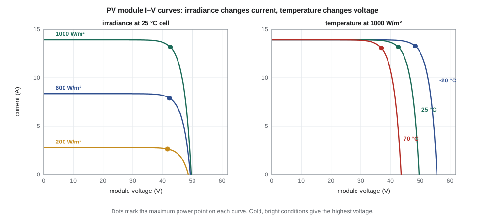
Two effects dominate field behaviour. Current scales almost linearly with irradiance, so a cloud halves the current but barely changes the voltage. Voltage falls as temperature rises: for crystalline silicon, Voc changes by about −0.25 to −0.30 % per °C, and maximum power by about −0.30 to −0.40 % per °C. Cells in sunlight run 20 to 35 °C above ambient, so on a hot summer day the cells may be at 60 to 70 °C and the module delivers noticeably less than its STC rating. On a cold, clear spring morning the opposite happens: high irradiance on cold cells gives the highest voltage and often the highest power of the year.
Strings, combiners and maximum power point tracking
Modules are connected in series to form strings, raising the voltage to a level the inverter can use and keeping conductor currents modest. Strings are connected in parallel, either at combiner boxes that feed a central inverter or directly at string inverters. Each parallel group operates at a common voltage chosen by the inverter's maximum power point tracking (MPPT) algorithm, which continuously adjusts the DC operating voltage to find the knee of the array's combined I–V curve. Common algorithms perturb the voltage slightly and observe whether power rises or falls, or compare incremental and instantaneous conductance.
Partial shading complicates the picture. A shaded cell cannot carry the string current, so bypass diodes across groups of cells in each module conduct to route current around it. The string's I–V curve then has more than one local maximum, and a simple tracker can get stuck on the wrong one. Modern inverters periodically sweep the whole voltage range to find the global maximum. Utility-scale plants on open farmland, like Birch Hill, suffer much less from shading than rooftops, but row-to-row shading in winter and snow cover still matter at northern latitudes.
Sizing the string
The number of modules in a string is set by two limits. The string's open-circuit voltage at the coldest expected temperature must not exceed the inverter's and the modules' maximum DC voltage, here 1500 V, because an inverter that is offline on a cold morning sees the full Voc of every string. At the other extreme, the string's maximum power voltage on the hottest day must stay above the bottom of the inverter's MPPT window, here 850 V, or the inverter cannot track the maximum power point and loses energy. Codes require the cold-temperature correction: the electrical code sets out how to adjust Voc for the lowest expected ambient temperature, using either the manufacturer's coefficient or a table.
import math, random
# Module datasheet (STC: 1000 W/m2, 25 C cell temperature)
VOC, VMP, ISC, IMP, PMAX = 49.6, 41.6, 13.9, 13.1, 545.0
B_VOC, G_PMAX = -0.0027, -0.0035          # temperature coefficients per deg C
VDC_MAX, MPPT_LO = 1500.0, 850.0          # inverter limits, V
T_MIN, T_CELL_HOT = -33.0, 70.0         # Fredericton design minimum ambient; hot cell temperature
voc_cold = VOC*(1 + B_VOC*(T_MIN - 25))
vmp_hot = VMP*(1 + B_VOC*(T_CELL_HOT - 25))
n_max = math.floor(VDC_MAX/voc_cold)
n_min = math.ceil(MPPT_LO/vmp_hot)
print(f"Voc at {T_MIN:.0f} C = {voc_cold:.1f} V -> at most {n_max} modules per string ({n_max*voc_cold:.0f} V)")
print(f"Vmp at {T_CELL_HOT:.0f} C cell = {vmp_hot:.1f} V -> at least {n_min} modules per string ({n_min*vmp_hot:.0f} V)")
n = n_max
print(f"Chosen: {n} modules/string, {n*PMAX/1000:.2f} kW per string")
# DC/AC ratio and clipping: a year of hourly plane-of-array irradiance from a simple random-sky model
random.seed(7)
def year():
    for d in range(365):
        dec = 23.45*math.sin(math.radians(360*(284 + d)/365))
        sky = random.choice((1.0, 0.95, 0.7, 0.45, 0.25, 0.1))      # clear to overcast
        for h in range(24):
            hang = 15*(h + 0.5 - 12); lat = math.radians(45.9)
            sin_alt = math.sin(lat)*math.sin(math.radians(dec)) + math.cos(lat)*math.cos(math.radians(dec))*math.cos(math.radians(hang))
            if sin_alt <= 0: continue
            g = 1040*sin_alt**1.1*sky*(1.12 if 60 < d < 150 else 1.0)   # tilted array, cold clear spring boost
            tcell = 5 + 25*math.sin(math.radians((d - 105)*360/365)) + g/1000*25
            yield g, tcell
AC = 10.0                                  # MW at the point of interconnection
for ratio in (1.1, 1.3, 1.5):
    dc = AC*ratio; e_dc = e_ac = 0.0
    for g, tc in year():
        p = dc*g/1000*(1 + G_PMAX*(tc - 25))*0.97      # 3 % wiring and mismatch losses
        e_dc += p; e_ac += min(p*0.985, AC)              # 98.5 % inverter efficiency, clip at AC limit
    print(f"DC/AC {ratio:.1f}: {dc:4.1f} MWdc, {e_ac:6.0f} MWh/yr AC, capacity factor {e_ac/(AC*8760)*100:4.1f} %, "
f"clipped {(e_dc*0.985 - e_ac)/(e_dc*0.985)*100:4.1f} %")Voc at -33 C = 57.4 V -> at most 26 modules per string (1492 V) Vmp at 70 C cell = 36.5 V -> at least 24 modules per string (877 V) Chosen: 26 modules/string, 14.17 kW per string DC/AC 1.1: 11.0 MWdc, 12153 MWh/yr AC, capacity factor 13.9 %, clipped 0.0 % DC/AC 1.3: 13.0 MWdc, 14745 MWh/yr AC, capacity factor 16.8 %, clipped 0.7 % DC/AC 1.5: 15.0 MWdc, 16450 MWh/yr AC, capacity factor 18.8 %, clipped 2.5 %
At the Fredericton design minimum of −33 °C, the module's Voc rises to 57.4 V, so at most 26 modules fit in a 1500 V string, giving 1492 V. On a hot day with cells at 70 °C, Vmp falls to 36.5 V, and at least 24 modules are needed to stay inside the MPPT window. Birch Hill uses 26, the maximum, because longer strings mean fewer strings, fewer combiner inputs and less wiring for the same DC capacity.
Worked problem
How many strings?
Birch Hill's array is 13.0 MW DC, built from 26-module strings of 545 W modules. How many strings and modules does it need, and how many strings feed each of the plant's four inverter stations?
Show solution
- Power per string: 26 × 545 W = 14.17 kW.
- \[N = \dfrac{13\,000\ \text{kW}}{14.17\ \text{kW}} \approx 918\ \text{strings}\]
- Modules: 918 × 26 = 23,868; per inverter station about 230 strings.
Answer: About 918 strings of 26 modules, roughly 23,900 modules, with about 230 strings per inverter station.
DC/AC ratio and clipping
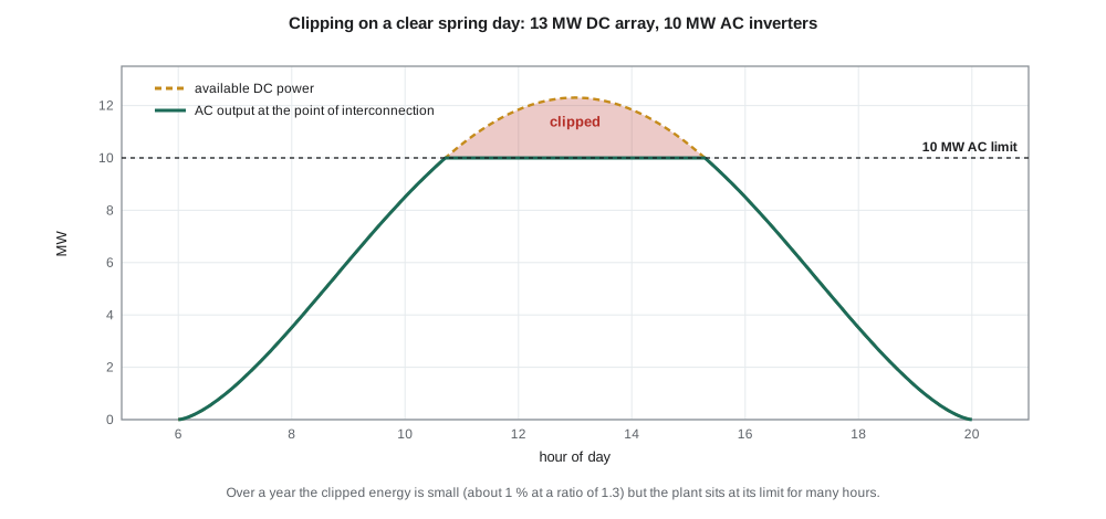
Birch Hill's array is rated 13 MW DC, but its inverters can deliver only 10 MW AC at the point of interconnection. The ratio of DC to AC capacity, here 1.3, is called the DC/AC ratio or inverter loading ratio. It is deliberate. Because the array rarely produces its full STC rating, an inverter sized to the array would sit partly idle most of the time. With a larger array, the inverter reaches full output for more hours, and the plant's energy per megawatt of interconnection capacity rises. When the array could produce more than the inverter's limit, the inverter moves its operating point off the maximum power point and the excess is lost. That loss is called clipping.
The program runs a simple year of hourly weather for three ratios. With a ratio of 1.1, almost nothing is clipped, but the capacity factor on the AC rating is only 13.9 %. At 1.3, clipping costs 0.7 % of the energy and the capacity factor rises to 16.8 %. At 1.5, clipping grows to 2.5 % but the plant still produces more, a capacity factor of 18.8 %. The developer picks the ratio from the cost of extra modules against the value of extra energy. For the utility, the important point is different: whatever the ratio, the plant's output at the point of interconnection never exceeds 10 MW, and a high ratio means it sits at that limit for many more hours a year.
A high DC/AC ratio also matters for storage. A battery connected on the DC side of the inverter, a DC-coupled design, can capture energy that would otherwise be clipped. Birch Hill uses an AC-coupled battery with its own inverter, which is simpler to control and study but cannot recover clipped energy directly. Lesson 5 compares the two arrangements.
From inverter to point of interconnection
Each of Birch Hill's four inverter stations combines a 2.75 MVA inverter with a step-up transformer from the inverter's 630 V output to the plant's 25 kV collector system. The collector cables run underground to a small plant substation, where a main breaker, revenue metering and the protection relays that the utility will specify sit at the point of interconnection (POI) with Larchmont's feeder. Four 2.75 MVA inverters give 11 MVA of apparent power, so the plant can deliver its full 10 MW while still supplying or absorbing reactive power at a power factor of about 0.91. That margin matters for the voltage control discussed in lesson 8.
Several electrical properties of the plant matter at the point of interconnection. The inverters and their transformers determine the plant's fault contribution and its harmonic emissions. The step-up transformer winding connections determine how the plant behaves during ground faults on the feeder, an issue Leo met in his protection term. The collector cables add capacitance, which supplies reactive power at night unless compensated. The plant controller coordinates all four inverters so that the utility sees a single resource with a single set of setpoints at the POI.
Safety: DC arcs, grounding and rapid shutdown
DC circuits in a PV array cannot be switched off by opening a breaker at the inverter: as long as light falls on the modules, the strings are energized. Firefighters on a burning roof, or technicians working on an array, face conductors at hundreds of volts that no switch upstream can de-energize. DC arcs are also hard to extinguish, because DC current has no natural zero crossing. Codes therefore require arc-fault detection on many PV circuits, ground-fault detection that interrupts faulted arrays, and, for systems on buildings, rapid shutdown equipment that reduces conductor voltage within the array to a safe level within seconds.
In Canada, Section 64 of the Canadian Electrical Code covers renewable energy systems, including PV source circuits, the cold-temperature voltage correction, overcurrent protection, disconnecting means and requirements for systems on buildings. Equipment must be certified to the applicable CSA standards. Ground-mounted utility-scale plants also follow the utility's interconnection requirements and, on the utility side of the point of interconnection, the utility's own construction standards.
For the utility, the most important safety concern sits on the AC side: the plant must not keep the feeder energized after the utility opens its breaker. That requirement, called anti-islanding, is one of the oldest in interconnection standards and is covered in lessons 6 and 9.
Common mistakes
MistakeSizing strings with the module's Voc at STC.
InsteadCorrect Voc for the coldest expected temperature; cold mornings give the highest voltage.
MistakeTreating clipping as a design error.
InsteadA DC/AC ratio above 1 is deliberate; clipping loses a small share of energy to raise output on ordinary days.
MistakeAssuming a plant can deliver reactive power at full real power with inverters rated exactly at its MW limit.
InsteadInverters need apparent power margin above the real power rating to supply or absorb reactive power.
MistakeAssuming opening the inverter's AC breaker makes the array safe.
InsteadPV strings stay energized whenever light falls on them.
Summary and key terms
- A PV cell is a diode whose photocurrent scales with irradiance; its voltage falls as temperature rises.
- Datasheet values are given at standard test conditions: 1000 W/m² and a 25 °C cell.
- Strings are sized so cold-weather Voc stays below the maximum DC voltage and hot-weather Vmp stays inside the MPPT window.
- MPPT algorithms keep the array at the knee of its I–V curve; partial shading can create multiple maxima.
- A DC/AC ratio above 1 raises energy per MW of interconnection at the cost of some clipping.
- Inverters need apparent power margin to provide reactive power at full output.
- PV DC circuits stay energized in daylight; codes require arc-fault, ground-fault and, on buildings, rapid shutdown protection.
- Standard test conditions (STC)
- Rating conditions of 1000 W/m² irradiance, 25 °C cell temperature and a standard spectrum.
- Maximum power point (MPP)
- The point on the I–V curve where voltage times current is greatest.
- Maximum power point tracking (MPPT)
- Inverter control that keeps the array at its maximum power point.
- String
- Modules connected in series to reach the inverter's operating voltage.
- DC/AC ratio
- Array DC capacity divided by inverter AC capacity, also called the inverter loading ratio.
- Clipping
- Energy lost when the array could exceed the inverter's AC limit.
- Point of interconnection (POI)
- The point where a resource connects to the utility system.
Practice problems
Work each problem on paper first, then reveal the answer to check.
A module has Voc 49.6 V and a coefficient of −0.27 %/°C. What is Voc at −20 °C?
Show answer
49.6 × (1 + 0.0027 × 45) ≈ 55.6 V.
With Voc of 55.6 V, how many modules fit in a 1500 V string?
Show answer
26 (1446 V); 27 would give 1501 V.
Why is the coldest temperature, not the hottest, used to check maximum string voltage?
Show answer
Voc rises as temperature falls.
A 12 MW DC array feeds 10 MW of inverters. What is the DC/AC ratio?
Show answer
1.2.
Why might a plant reach its AC limit more often in spring than in summer?
Show answer
Cold cells and clear skies give higher module output than hot summer conditions.
Four 2.75 MVA inverters deliver 10 MW. How much reactive power can they supply at that output?
Show answer
√(11² − 10²) ≈ 4.6 Mvar.
Lesson quiz · 5 questions
Score 60% or more to complete this lesson.
Create a free account to save your progress, take quizzes and earn a certificate.