
ELE-351 · Lesson 2 of 12 · 24 min
Sampling, aliasing and reconstruction
Every DSP system begins and ends with a conversion between continuous and discrete time. ELE-250 proved the sampling theorem: a signal with no energy at or above f_s/2 can be rebuilt perfectly from samples taken at rate f_s. Real signals, though, are never perfectly band-limited, real filters never cut off perfectly, and real converters do not produce ideal impulses. This lesson is about the engineering that sits between the theorem and a working product: deciding how fast to sample, how much anti-aliasing filtering is needed, how oversampling and sigma-delta converters make that filtering cheap, when a signal can deliberately be sampled below its highest frequency, how a DAC rebuilds the waveform, and how clock jitter limits everything.
Aliasing revisited
Sampling at f_s cannot tell a frequency f from f + kf_s for any integer k, because the samples are identical. A component at frequency f therefore appears, after sampling, at the alias frequency inside the range 0 to f_s/2 found by folding: subtract the nearest multiple of f_s and take the magnitude. The folding frequency f_s/2, the Nyquist frequency, acts like a mirror. Once a component has been aliased, nothing downstream can tell it from a genuine signal at the alias frequency, which is why aliasing must be prevented before the converter, not corrected after it.
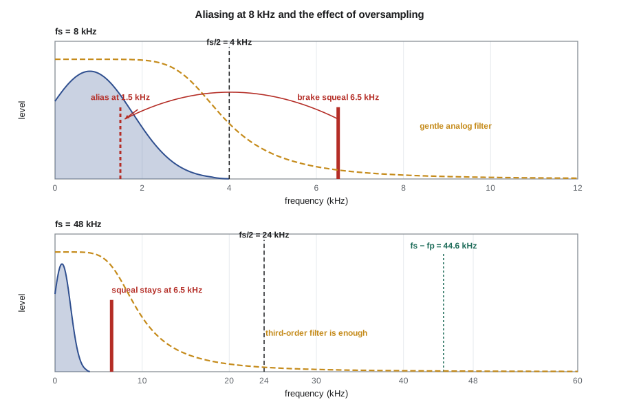
Revision B of the APS-2 sampled at 8 kHz behind a modest analog filter, and ELE-250 traced one of its field complaints to brake squeal. A bus brake squealing at 6.5 kHz folded to |6.5 − 8| = 1.5 kHz, right in the middle of the speech band, and the level meter read it as ambient noise even after the bus had stopped squealing at the human ear's threshold. Revision C samples at 48 kHz, so the 6.5 kHz squeal is now represented at its true frequency, and an A-weighting filter can give it the correct, modest weight. Aliasing has not disappeared, though. It has moved: when the firmware decimates to 16 kHz, anything between 8 and 24 kHz that the decimation filter fails to remove will fold back into 0 to 8 kHz. Lesson 11 designs that filter.
How much anti-aliasing filtering?
The anti-aliasing filter must attenuate everything that would fold into the band of interest by enough that the folded products fall below the noise or the required accuracy. If the wanted band extends to f_p and the converter samples at f_s, the first frequency that folds onto f_p is f_s − f_p, so the filter must reach its stop-band attenuation A by f_stop = f_s − f_p. Note that it is f_s − f_p, not f_s/2, that matters if only the band 0 to f_p is used: frequencies between f_s/2 and f_s − f_p fold into the unused region between f_p and f_s/2 and can be removed later digitally.
For a Butterworth low-pass filter with its 3 dB point near f_p, the attenuation at f_stop grows by about 20 dB per decade per pole, so the order needed for attenuation A in decibels is approximately the expression below. The table that follows shows why low sample rates are expensive. With speech up to 3.4 kHz sampled at 8 kHz, f_stop is 4.6 kHz, barely a third of an octave above f_p, and 60 dB needs a filter of order 23, which nobody builds. Real 8 kHz designs accept less attenuation and rely on speech having little energy near 4 kHz. Sampling the same band at 48 kHz moves f_stop to 44.6 kHz, more than a decade above f_p, and a third-order filter suffices.
| Sampling | f_p | f_stop = f_s − f_p | Order for 60 dB | Order for 90 dB |
|---|---|---|---|---|
| 8 kHz | 3.4 kHz | 4.6 kHz | 23 | 35 |
| 16 kHz | 3.4 kHz | 12.6 kHz | 6 | 8 |
| 48 kHz | 3.4 kHz | 44.6 kHz | 3 | 5 |
| 48 kHz | 20 kHz | 28 kHz | 21 | 31 |
| 3.072 MHz (64× oversampled) | 20 kHz | 3.052 MHz | 2 | 3 |
Oversampling and sigma-delta converters
The last row of the table explains how modern audio codecs work. Their sigma-delta modulators sample at a high multiple of the output rate, typically 64 or 128 times, so an output rate of 48 kHz means a modulator clock of 3.072 or 6.144 MHz. The analog anti-aliasing filter only has to protect the band around that very high rate, which a single resistor and capacitor almost do. The modulator produces a coarse, very fast stream, and a digital decimation filter inside the codec then removes everything above about 20 kHz with a sharp, linear-phase response and reduces the rate to 48 kHz. Lesson 3 explains how the coarse stream becomes 24 good bits, and lesson 11 explains decimation filters. For Amara, the practical consequence is that the codec's own digital filter now defines the anti-aliasing performance: its data sheet specifies a pass band to about 0.45f_s and a stop band beyond about 0.55f_s with roughly 80 to 100 dB of rejection, values typical of current audio converters.
A narrow region near 24 kHz is therefore in the transition band: a strong ultrasonic tone at, say, 25 kHz would be only partly removed and would alias to 23 kHz. That does not matter for the APS-2, because 23 kHz is outside anything the firmware uses and is removed again when the signal is decimated to 16 kHz. What does matter is the analog front end. The modulator samples at 3.072 MHz, so energy near 3.072 MHz ± 20 kHz would fold straight into the audio band. The microphone cable can pick up AM broadcast and switching noise, and the class D amplifier on the same board switches at several hundred kilohertz. The RF filter at the input from ELE-340 and careful board layout are still needed.
Bandpass sampling
The sampling theorem in its usual form assumes a low-pass signal, but what it really requires is that the spectral copies created by sampling do not overlap. A signal confined to a band from f_L to f_H, with bandwidth B = f_H − f_L, can be sampled at a rate as low as about 2B, far below 2f_H, if the rate is chosen so that the band folds cleanly into one Nyquist zone. This is bandpass sampling, or undersampling, and it lets a digital radio sample an intermediate frequency directly. The allowed rates come in windows indexed by an integer k, the number of the Nyquist zone the band occupies.
The TLR-1 radio of ELE-350 uses a 10.7 MHz intermediate frequency with a 200 kHz-wide filter, so its IF signal lies between 10.6 and 10.8 MHz. Amara's colleagues are considering a future version that digitizes the IF directly. The code below lists the windows. The window for k = 9 runs from 2.400 to 2.650 MHz. Its lower edge, 2.4 MHz, would put the top of the band exactly on the folding frequency, with no room for the filter skirts, so Amara picks 2.5 MHz from the middle of the window. The band then folds to 0.6 to 0.8 MHz, with guard bands of 0.6 MHz below and 0.45 MHz above, inside the first Nyquist zone of 0 to 1.25 MHz. Bandpass sampling has two prices. The converter's analog input bandwidth and its sample-and-hold must still handle 10.8 MHz, and every source of noise and interference in all the folded zones lands on top of the signal, so an analog bandpass filter in front is essential. Clock jitter, discussed below, also matters far more at 10.7 MHz than at audio.
Reconstruction and the zero-order hold
The ideal reconstruction of the theorem places a sinc pulse at every sample, which is not causal and cannot be built. A real DAC holds each output value for one sample period, a zero-order hold. The output is a staircase whose spectrum is the ideal spectrum multiplied by a sinc envelope and accompanied by images, copies of the signal spectrum around every multiple of f_s. The sinc envelope causes droop, a gentle loss of high frequencies within the band; the images must be removed by an analog reconstruction filter.
At a 48 kHz output rate the droop at 3.4 kHz is only 0.07 dB, and at 20 kHz it is 2.6 dB. The images of a 3.4 kHz tone sit at 44.6 and 51.4 kHz, beyond hearing but not beyond the reach of the amplifier and speaker, which could waste power or interact with the class D switching. Audio DACs avoid the problem the same way ADCs do: an internal interpolation filter raises the rate by 8 or more before the hold, which pushes the first images to hundreds of kilohertz, where a simple analog filter removes them. Where droop matters, for example in an instrumentation DAC running near its Nyquist limit, a digital pre-emphasis filter with the inverse sinc response corrects it before conversion.
Worked problem
Droop and image levels at two output rates
The old APS-2 played voice through an 8 kHz DAC with a zero-order hold. Find the droop at 3.4 kHz and the level of the first image of a 3.4 kHz tone, before any analog filtering, and compare them with a 48 kHz DAC.
Show solution
- At 8 kHz, the image of a 3.4 kHz tone appears at 8 − 3.4 = 4.6 kHz.
- \[\text{droop}(3.4) = 20\log_{10}\Big|\frac{\sin(\pi\,0.425)}{\pi\,0.425}\Big| = -2.75\ \text{dB}\]
- \[\text{image}(4.6) = 20\log_{10}\Big|\frac{\sin(\pi\,0.575)}{\pi\,0.575}\Big| = -5.4\ \text{dB}\]
- At 48 kHz the droop at 3.4 kHz is −0.07 dB and the first image, at 44.6 kHz, is about −22.4 dB.
Answer: The 8 kHz DAC loses almost 3 dB at the top of the speech band and leaves an image only 2.7 dB below the tone itself, just above the band, where it is audible as a harsh edge unless the reconstruction filter is steep. At 48 kHz both problems almost vanish. This is part of why revision C plays its 16 kHz voice prompts through an interpolator and a 48 kHz DAC.
Clock jitter
Sampling assumes the samples are taken at exactly nT. If the sampling instants wander by a random time error with standard deviation σ_j, a signal that is changing quickly is sampled at slightly the wrong value. For a full-scale sinusoid of frequency f, the error behaves like noise, and the best achievable signal-to-noise ratio is set by the jitter alone. The limit depends on the product of signal frequency and jitter, not on the sample rate, which is why jitter is a minor concern for audio but a major one for IF sampling.
import math
def alias(f, fs):
    k = round(f / fs)
    return abs(f - k * fs)
print("aliases of brake squeal 6.5 kHz:", [round(alias(6500, fs)) for fs in (8000, 16000, 48000)])
print("alias of 25 kHz at 48 kHz:", alias(25000, 48000), " of 11 kHz at 16 kHz:", alias(11000, 16000))

def bw_order(A, fp, fstop):
    return math.ceil(math.log10(10 ** (A / 10) - 1) / (2 * math.log10(fstop / fp)))
for fs, fp in ((8000, 3400), (16000, 3400), (48000, 3400), (48000, 20000), (3.072e6, 20000)):
    print(f"fs = {fs/1000:8.3f} kHz, fp = {fp/1000:4.1f} kHz: order {bw_order(60, fp, fs - fp):2d} for 60 dB, {bw_order(90, fp, fs - fp):2d} for 90 dB")

fL, fH = 10.6e6, 10.8e6; B = fH - fL
print("bandpass sampling windows for 10.6-10.8 MHz (MHz):")
for k in range(int(fH // B), 0, -1):
    lo = 2 * fH / k
    hi = 2 * fL / (k - 1) if k > 1 else float('inf')
    if lo <= hi and 8 <= k <= 12:
        print(f"  k = {k:2d}: {lo/1e6:.3f} to {hi/1e6:.3f}")
fs = 2.5e6
print(f"10.6 and 10.8 MHz at 2.5 MHz fold to {alias(fL, fs)/1e6:.2f} and {alias(fH, fs)/1e6:.2f} MHz")

def droop(f, fs):
    x = math.pi * f / fs
    return 20 * math.log10(abs(math.sin(x) / x))
for fs in (8000, 48000):
    print(f"ZOH at {fs} Hz: droop at 3.4 kHz {droop(3400, fs):6.2f} dB, first image {droop(fs - 3400, fs):6.1f} dB")
print(f"droop at 20 kHz, 48 kHz DAC: {droop(20000, 48000):.2f} dB")
for f, sj in ((20e3, 1e-9), (10.7e6, 1e-12), (10.7e6, 10e-12)):
print(f"jitter {sj*1e12:6.0f} ps at {f/1e6:6.3f} MHz: SNR limit {-20*math.log10(2*math.pi*f*sj):5.1f} dB")aliases of brake squeal 6.5 kHz: [1500, 6500, 6500] alias of 25 kHz at 48 kHz: 23000 of 11 kHz at 16 kHz: 5000 fs = 8.000 kHz, fp = 3.4 kHz: order 23 for 60 dB, 35 for 90 dB fs = 16.000 kHz, fp = 3.4 kHz: order 6 for 60 dB, 8 for 90 dB fs = 48.000 kHz, fp = 3.4 kHz: order 3 for 60 dB, 5 for 90 dB fs = 48.000 kHz, fp = 20.0 kHz: order 21 for 60 dB, 31 for 90 dB fs = 3072.000 kHz, fp = 20.0 kHz: order 2 for 60 dB, 3 for 90 dB bandpass sampling windows for 10.6-10.8 MHz (MHz): k = 12: 1.800 to 1.927 k = 11: 1.964 to 2.120 k = 10: 2.160 to 2.356 k = 9: 2.400 to 2.650 k = 8: 2.700 to 3.029 10.6 and 10.8 MHz at 2.5 MHz fold to 0.60 and 0.80 MHz ZOH at 8000 Hz: droop at 3.4 kHz -2.75 dB, first image -5.4 dB ZOH at 48000 Hz: droop at 3.4 kHz -0.07 dB, first image -22.4 dB droop at 20 kHz, 48 kHz DAC: -2.64 dB jitter 1000 ps at 0.020 MHz: SNR limit 78.0 dB jitter 1 ps at 10.700 MHz: SNR limit 83.4 dB jitter 10 ps at 10.700 MHz: SNR limit 63.4 dB
The results confirm the table and the example, and they put numbers on the jitter argument. A 1 ns jitter, which is poor for a crystal clock but possible for a clock recovered from a noisy digital interface, still allows 78 dB at 20 kHz. At 10.7 MHz, a clock with 1 ps of jitter limits the SNR to about 83 dB, and 10 ps limits it to 63 dB, which would waste several bits of a good converter. Direct IF sampling therefore needs a low-jitter clock, often a dedicated crystal oscillator rather than the microcontroller's clock.
A sampling checklist
Amara turns the lesson into a checklist that she attaches to the revision C design review. State the band of interest and the required dynamic range. Choose the sample rate and identify f_s − f_p, the first frequency that folds into the band. List the interference that might be present above the band, including ultrasonic sources and radio-frequency pickup. Decide what attenuation is needed and where it comes from: analog filter, converter's digital filter or later decimation filtering. Check the reconstruction side for droop and images. Finally, check that the clock jitter is small enough for the highest frequency being sampled. With the codec chosen, the checklist shows that the remaining risks are radio-frequency pickup near the modulator rate and the decimation filter of lesson 11.
Common mistakes
MistakeDesigning the anti-aliasing filter to be low only at f_s/2.
InsteadOnly f_s − f_p must be protected if the band f_p to f_s/2 is discarded later; this can relax the filter considerably.
MistakeAssuming a sigma-delta codec needs no analog input filtering.
InsteadIt still aliases energy near multiples of its modulator rate; an RF filter and good layout are required.
MistakeChoosing any bandpass sample rate above 2B.
InsteadThe rate must fall inside one of the allowed windows; a rate between windows makes the folded copies overlap.
MistakeIgnoring the images from a zero-order-hold DAC.
InsteadImages at f_s ± f can be only a few decibels below the signal; interpolation or a reconstruction filter is needed.
Summary and key terms
- A component at f appears after sampling at |f − kf_s|, folded into 0 to f_s/2; aliasing cannot be undone afterwards.
- The anti-aliasing filter must reach its stop-band attenuation by f_s − f_p, and the required order falls rapidly with oversampling.
- Sigma-delta codecs oversample heavily so a simple analog filter suffices, and their digital decimation filter sets the effective anti-aliasing response.
- Bandpass signals can be sampled near twice their bandwidth if the rate lies in an allowed window.
- A zero-order-hold DAC causes sinc droop and images at multiples of f_s; interpolating DACs push the images far away.
- Clock jitter limits SNR to −20 log₁₀(2πfσ_j), which matters most at high signal frequencies.
- Nyquist frequency
- Half the sample rate, the folding frequency of the sampled spectrum.
- Alias
- A frequency component that appears at a false frequency because of sampling.
- Anti-aliasing filter
- An analog low-pass or bandpass filter placed before the sampler to remove components that would alias.
- Oversampling
- Sampling at a rate well above twice the band of interest.
- Bandpass sampling
- Sampling a band-limited signal at a rate set by its bandwidth rather than its highest frequency.
- Zero-order hold
- A DAC output that holds each sample value constant for one sample period.
- Image
- A copy of the signal spectrum around a multiple of the sample rate at the output of a DAC.
- Clock jitter
- Random variation in the timing of sampling instants.
Practice problems
Work each problem on paper first, then reveal the answer to check.
A 14 kHz tone reaches a converter sampling at 16 kHz with no filter. Where does it appear?
Show answer
|14 − 16| = 2 kHz.
Speech up to 4 kHz is sampled at 12 kHz. What is the first frequency that folds into the band?
Show answer
12 − 4 = 8 kHz.
Using the formula, what Butterworth order gives 40 dB at 8 kHz with f_p = 4 kHz?
Show answer
log₁₀(10⁴ − 1)/(2 log₁₀ 2) = 6.64, so order 7.
A band from 70 to 80 MHz is to be bandpass sampled. What is the highest usable zone k and the corresponding rate range?
Show answer
k = ⌊80/10⌋ = 8: 2(80)/8 = 20 MHz to 2(70)/7 = 20 MHz, a single rate with no margin; use k = 7, 22.9 to 23.3 MHz.
Find the zero-order-hold droop at 10 kHz for a 44.1 kHz DAC.
Show answer
x = π(10/44.1) = 0.712; sin x/x = 0.917, −0.75 dB.
What jitter limits a 100 kHz full-scale signal to an SNR of 96 dB?
Show answer
σ_j = 10^(−96/20)/(2π × 10⁵) = 25 ps.
Lesson quiz · 5 questions
Score 60% or more to complete this lesson.
Create a free account to save your progress, take quizzes and earn a certificate.