
ELE-315 · Lesson 8 of 12 · 26 min
Serial communication I: UART and RS-485
Almost every embedded system talks to something else, and the oldest, simplest and most widely used way to do it is the asynchronous serial port. A universal asynchronous receiver-transmitter, or UART, sends bytes one bit at a time over a single wire in each direction, with no shared clock. The two ends agree in advance on the bit rate and frame format, and the receiver recovers timing from the start of each byte. UARTs connect microcontrollers to modems, GPS receivers, Bluetooth modules, debug consoles and each other. At logic levels they reach only across a board or a short cable; paired with a differential transceiver such as RS-485, the same frames travel over a kilometre of twisted pair and connect dozens of devices on one bus. This lesson covers the UART frame, baud-rate generation and its error budget, the receiver's sampling, errors and buffering, flow control, and the physical layers that carry UART frames over distance.
The NS-4 uses two UARTs. One connects to the cellular modem on the same board. The other drives an RS-485 transceiver whose cable runs 40 m down the pole to the roadside cabinet, where a technician's laptop or the NS-5 cabinet controller polls the counter. The old firmware's RS-485 link worked on the bench and failed intermittently in the field. Dev Okafor, the field technician, has a drawer full of returned cabinet adapters, and Jonah's job this week is to work out why.
The UART frame
An idle UART line sits at logic high, called mark. A frame begins with a start bit, a single bit time at logic low, called space. Then follow five to nine data bits, almost always eight, sent least significant bit first; an optional parity bit; and one or two stop bits at logic high, after which the line either idles or begins the next start bit. The common shorthand 8N1 means eight data bits, no parity, one stop bit, giving 10 bit times per byte. At 115,200 baud, each bit lasts 8.68 µs and each byte 86.8 µs, so the maximum throughput is 11,520 bytes per second. Baud means symbols per second; for a UART, one symbol is one bit.
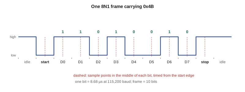
Parity adds one bit that makes the number of ones in the data and parity together even or odd. It detects any single-bit error in the frame but not two. Most modern protocols leave parity off and protect whole messages with a checksum or cyclic redundancy check, which catches far more errors for the same overhead. The NS-4's cabinet protocol uses 8N1 with a 16-bit CRC on each message.
Receiver timing and the baud-rate error budget
Because there is no shared clock, the receiver times each bit from the falling edge of the start bit. A typical UART samples the line at 16 times the baud rate. When it detects a falling edge, it waits eight sample clocks to reach the middle of the start bit, confirms the line is still low, and then samples every 16 sample clocks thereafter, near the middle of each data bit and the stop bit. Many UARTs take three samples around the centre and use a majority vote, which rejects short noise spikes and sets a noise flag when the samples disagree.
If the transmitter and receiver clocks differ, the receiver's sampling points drift relative to the incoming bits. The error accumulates through the frame and is worst at the stop bit, the last bit sampled. For a 10-bit frame, the stop bit's centre is 9.5 bit times after the start edge, and the sample must land within that bit, so it may drift by just under half a bit. The receiver's edge detection adds up to one sample clock, 1/16 of a bit, of uncertainty. That leaves a total clock mismatch budget of roughly
shared between the two ends. Allowing margin for the line's rise and fall times and for the majority-vote window, a common design rule is to keep each end within about 2 percent of the nominal rate. A crystal oscillator, accurate to better than 0.01 percent, contributes nothing significant. The error that matters is the quantization in the baud-rate divider, and the drift of internal RC oscillators, which can be off by 1 to 3 percent across temperature unless trimmed.
Generating the baud rate
A UART derives its sample clock by dividing the peripheral clock. With 16 times oversampling, the divider is the peripheral clock divided by 16 times the baud rate. If the divider register accepts only integers, the actual rate differs from the requested one. Many UARTs add a fractional part, typically four bits giving sixteenths, or allow eight times oversampling to reach higher rates. The divisor and the resulting error are easy to compute, and every embedded engineer has made a table of them at some point.
Worked problem
115,200 baud from a 24 MHz clock
The NS-4's RS-485 UART sits on a peripheral bus clocked at 24 MHz. Find the integer divisor and the error for 115,200 baud with 16 times oversampling, then the fractional divisor with four fraction bits.
Show solution
- \[ \frac{24 \times 10^6}{16 \times 115200} = 13.0208\]
- With an integer divisor of 13, the actual rate is 24 MHz ÷ (16 × 13) = 115,385 baud.
- \[ \text{error} = \frac{115385}{115200} - 1 = +0.16\ \%\]
- With four fraction bits, the divisor becomes 13 + 0/16 = 13.0000 or 13 + 1/16 = 13.0625; the nearer is 13.0000, so the fraction does not help here.
Answer: Use a divisor of 13, giving +0.16 percent error, far inside the 2 percent budget. The other end, a cabinet controller with its own crystal, adds a negligible error.
# Baud-rate divisor and error for common rates and clocks, 16x oversampling, 4 fraction bits
rates = [9600, 19200, 57600, 115200, 230400, 460800, 921600]
clocks = [8e6, 24e6, 48e6]
def brr(fclk, baud, frac_bits=4):
    div = fclk / (16 * baud)
    q = round(div * 2**frac_bits) / 2**frac_bits   # nearest representable divisor
    actual = fclk / (16 * q)
    return q, actual, 100 * (actual / baud - 1)
print("baud     " + "".join(f"{c/1e6:>6.0f} MHz: div / err%     " for c in clocks))
for b in rates:
    row = f"{b:<8d} "
    for c in clocks:
        q, actual, err = brr(c, b)
        flag = " !" if abs(err) > 2 else "  "
        row += f"     {q:9.4f} / {err:+6.2f}{flag}  "
    print(row)
# Total mismatch budget for a 10-bit frame, sampled mid-bit, edge uncertainty 1/16 bit
print(f"budget: {100*(0.5 - 1/16)/9.5:.2f}% total between both ends")baud 8 MHz: div / err% 24 MHz: div / err% 48 MHz: div / err% 9600 52.0625 / +0.04 156.2500 / +0.00 312.5000 / +0.00 19200 26.0625 / -0.08 78.1250 / +0.00 156.2500 / +0.00 57600 8.6875 / -0.08 26.0625 / -0.08 52.0625 / +0.04 115200 4.3125 / +0.64 13.0000 / +0.16 26.0625 / -0.08 230400 2.1875 / -0.79 6.5000 / +0.16 13.0000 / +0.16 460800 1.0625 / +2.12 ! 3.2500 / +0.16 6.5000 / +0.16 921600 0.5625 / -3.55 ! 1.6250 / +0.16 3.2500 / +0.16 budget: 4.61% total between both ends
The table shows the pattern. At low rates, every clock works. At high rates, slow clocks run out of resolution: from 8 MHz, 921,600 baud needs a divisor of 0.54, below the minimum of 1 that most UARTs accept with 16 times oversampling, and even 460,800 baud comes out 2.1 percent fast. Switching to 8 times oversampling doubles the available rate at the cost of noise immunity. Some designers choose crystal frequencies such as 7.3728 MHz or 14.7456 MHz precisely because they divide evenly into all the standard baud rates.
Receiving reliably: errors, buffering and framing
A UART receiver reports several error conditions. An overrun means a new byte finished arriving before software read the previous one; the data are lost, and the cause is always software latency or a missing buffer. A framing error means the stop bit was sampled low, usually because of a baud mismatch, noise, or a break condition, in which the transmitter holds the line low for longer than a whole frame, sometimes used deliberately as a reset or attention signal. A noise flag means the majority-vote samples disagreed. A parity error, when parity is enabled, means the parity check failed. Firmware should count each kind of error rather than silently discard it; error counts are among the most useful field diagnostics an embedded product can report.
Most UARTs have a very small receive buffer, sometimes one byte, sometimes a FIFO of 8 or 16 bytes. Firmware must empty it faster than bytes arrive, which at high rates means interrupts with a ring buffer, as in lesson 7, or DMA into a circular buffer. Many UARTs also detect an idle line, a full frame time with no start bit, and raise an interrupt; combined with DMA, this lets firmware receive variable-length messages without handling each byte. Messages themselves need framing at a higher level: a length prefix, a delimiter that cannot appear in the data, or byte stuffing such as consistent overhead byte stuffing, so the receiver can find message boundaries after an error.
/* Receive variable-length messages with DMA into a circular buffer plus idle-line detection.
   The DMA writes continuously; the idle interrupt tells the main loop how far it has got. */
#define RXBUF 512u
static uint8_t rxbuf[RXBUF];
static volatile uint16_t rx_wr;            /* DMA write position, sampled at idle */

void rs485_rx_start(void)
{
    DMA1_CH5->PAR  = (uint32_t)&USART1->DR;
    DMA1_CH5->MAR  = (uint32_t)rxbuf;
    DMA1_CH5->CNDTR = RXBUF;
    DMA1_CH5->CCR  = DMA_CCR_MINC | DMA_CCR_CIRC | DMA_CCR_EN;
    USART1->CR3   |= USART_CR3_DMAR;
    USART1->CR1   |= USART_CR1_IDLEIE | USART_CR1_RE | USART_CR1_UE;
}

void USART1_IRQHandler(void)
{
    if (USART1->SR & USART_SR_IDLE) {
        (void)USART1->DR;                  /* read SR then DR clears IDLE */
        rx_wr = (uint16_t)(RXBUF - DMA1_CH5->CNDTR);
        msg_ready = 1;                     /* main loop parses from its read index to rx_wr */
    }
}
Flow control
If a receiver cannot keep up, it needs a way to tell the sender to pause. Hardware flow control uses two extra wires: the receiver deasserts its request-to-send output, wired to the sender's clear-to-send input, when its buffer is nearly full. Many UARTs implement this automatically. Software flow control sends special characters, XOFF to pause and XON to resume, in the data stream, which works over a single pair but forbids those byte values in binary data. Cellular modems almost always use hardware flow control at high rates, because the modem's internal buffers can fill while it waits for the network. The NS-4's modem link runs at 460,800 baud with hardware flow control enabled after Jonah finds that the old firmware had left it off, and that a burst of modem status messages during network registration could overrun the receiver.
Physical layers: logic level, RS-232 and RS-485
A UART's pins produce logic-level signals, 0 V and 3.3 V on the NS-4. That works between chips on one board and over short cables, but logic levels share a ground with every other current on the board, have little noise margin and cannot drive long cables. Two standard physical layers extend UART frames. RS-232, the traditional serial port, uses inverted, bipolar levels of roughly plus and minus 5 to 12 V, referenced to ground, for point-to-point links up to about 15 m. It is still found on industrial equipment and test instruments, usually reached today through a USB adapter.
RS-485 is differential: each signal uses a twisted pair, A and B, and the receiver looks only at the voltage difference between them, at least 200 mV for a valid level. Noise picked up equally on both wires, common-mode noise, cancels. A driver produces at least 1.5 V of differential signal into the bus load. RS-485 supports a common-mode range of −7 V to +12 V, which tolerates ground differences between distant devices, and it is a multidrop standard: up to 32 standard unit loads, or more with fractional-load transceivers, on one bus. Because all devices share one pair, RS-485 is usually half duplex: only one device drives at a time, and each transceiver has a driver-enable input that firmware controls.
| Property | Logic-level UART | RS-232 | RS-485 |
|---|---|---|---|
| Signalling | Single-ended, 0 and 3.3 V | Single-ended, about ±5 to ±12 V, inverted | Differential pair, at least 1.5 V driven, 200 mV threshold |
| Topology | Point to point | Point to point | Multidrop bus, 32 unit loads or more |
| Typical reach | Under 1 m | About 15 m | Up to about 1,200 m at low rates |
| Duplex | Full | Full | Usually half (one pair); full with two pairs |
| Common uses | Chip to chip, debug console | Instruments, legacy equipment | Industrial buses, building control, roadside equipment |
Designing the RS-485 link
An RS-485 bus is a transmission line. At the NS-4's 40 m length and 115,200 baud, the bit time of 8.7 µs is long compared with the cable's propagation delay of about 200 ns, so reflections settle well within each bit. A common rule of thumb is that the product of cable length in metres and data rate in bits per second should stay below about 10⁸; the NS-4's link, at 4.6 × 10⁶, is far inside that. Even so, a bus should be terminated with a resistor matching the cable's characteristic impedance, usually 120 Ω, at each end of the cable, and only at the ends. Devices along the bus connect with short stubs.
When no driver is active, a terminated bus floats near 0 V differential, inside the receiver's undefined region, and the receivers may output random bits, which the UARTs interpret as start bits and garbage. Fail-safe biasing fixes this: a pull-up on A and a pull-down on B, typically a few hundred ohms each at one point on the bus, hold the idle differential above 200 mV. Many modern transceivers include fail-safe receivers that output high for an open, shorted or idle bus, which reduces the need for external bias.
Worked problem
Fail-safe bias resistors
An RS-485 bus has 120 Ω termination at each end, giving 60 Ω across A and B. Bias resistors from A to 3.3 V and from B to ground, of equal value R, must hold at least 200 mV across the pair when the bus is idle. Find the largest R, and check the result with a margin of 50 percent.
Show solution
- The bias network is R, then 60 Ω, then R in series across 3.3 V.
- \[ V_{AB} = 3.3\ \text{V} \cdot \frac{60}{2R + 60} \ge 0.2\ \text{V}\]
- \[ 2R + 60 \le \frac{3.3 \times 60}{0.2} = 990\ \Omega \ \to\ R \le 465\ \Omega\]
- With 50 percent margin, 300 mV: 2R + 60 ≤ 660 Ω, so R ≤ 300 Ω. A standard 270 Ω gives 3.3 × 60 ÷ 600 = 330 mV.
Answer: Use 270 Ω bias resistors at one point on the bus, giving about 330 mV of idle differential. The bias draws about 5.5 mA from 3.3 V, which matters on a solar-powered node, so the NS-4 places the bias at the cabinet end, where mains power is available.
The last and most common RS-485 bug is driver-enable timing. In half duplex, the transmitting device must enable its driver before the first start bit and disable it after the last stop bit has left the shift register, then release the bus so the other device can answer. Firmware that disables the driver when the transmit data register becomes empty, rather than when transmission is complete, cuts off the last byte's final bits; and firmware that disables it late collides with the reply. This is exactly what Jonah finds in the old NS-4 code: the driver was turned off on the data-register-empty flag, which fires one byte early. On the bench, the cabinet adapter's generous parser tolerated a truncated CRC byte about half the time; in the field, with longer replies, it failed. Many UARTs now drive the enable pin automatically, with programmable setup and hold times, and Jonah switches to that mode.
/* Half-duplex RS-485 transmit with driver enable handled by the UART hardware.
   DEM: driver enable mode; DEAT/DEDT: assertion and deassertion times in sample clocks. */
void rs485_init(void)
{
    USART1->CR3 |= USART_CR3_DEM;                         /* DE pin follows transmission */
    USART1->CR1 |= (8u << USART_CR1_DEAT_Pos)             /* 0.5 bit before start */
                 | (8u << USART_CR1_DEDT_Pos);            /* 0.5 bit after last stop */
}

/* Software alternative: release the driver only on transmission complete (TC), never on TXE. */
void USART1_TC_handler(void)
{
    if (USART1->ISR & USART_ISR_TC) {
        USART1->ICR = USART_ICR_TCCF;
        gpio_clear(RS485_DE);
    }
}
Two hardware details complete the link. Long cables between a pole and a cabinet pick up surges from lightning and switching, so the NS-4 adds transient voltage suppressors on A and B and a common-mode choke. And because the cabinet and the pole-top node may sit at slightly different ground potentials, Ines Carvalho, the hardware lead, specifies an isolated transceiver for the NS-5, which carries the data across an internal barrier and lets the cable's ground float.
Debug consoles and logging
The humblest UART use is often the most valuable. A spare UART connected to a header, running a simple text console, lets developers and field technicians print logs, query status and change settings without special tools. Printing is slow, though: a 60-character log line at 115,200 baud takes over 5 ms to transmit, so logging must go through a buffer drained by interrupts or DMA, never a loop that waits for each character, or it will distort the timing it is trying to observe. Lesson 12 returns to debugging tools.
Common mistakes
MistakeUsing an internal RC oscillator for a UART without checking its accuracy.
InsteadCheck the baud error budget, about 2 percent per end; trim the oscillator or use a crystal for reliable links.
MistakeDisabling the RS-485 driver when the transmit data register empties.
InsteadDisable it on transmission complete, or use the UART's hardware driver-enable mode.
MistakeTerminating an RS-485 bus at every device, or not at all.
InsteadTerminate both ends of the cable only, with resistors matching the cable impedance.
MistakeLeaving an idle RS-485 bus undefined.
InsteadUse fail-safe bias resistors or fail-safe transceivers.
MistakeDiscarding UART error flags.
InsteadCount overruns, framing and noise errors; they are vital field diagnostics.
Summary and key terms
- A UART frame has a start bit, usually eight data bits sent least significant first, optional parity and a stop bit.
- The receiver times bits from the start edge, so total clock mismatch must stay under about 4.6 percent for 10-bit frames.
- Baud-rate divisor quantization and RC oscillator drift are the main sources of error.
- Overruns indicate software latency; framing errors indicate baud mismatch, noise or a break.
- Use interrupts with ring buffers or DMA with idle detection, and frame messages with length or delimiters and a CRC.
- RS-485 is differential and multidrop, needs end termination and fail-safe bias, and is usually half duplex.
- The RS-485 driver must be released only after the last stop bit has been sent.
- UART
- A peripheral that sends and receives asynchronous serial frames.
- Baud rate
- The number of symbols per second; for a UART, bits per second.
- 8N1
- Eight data bits, no parity, one stop bit.
- Overrun
- Loss of a received byte because the previous one had not been read.
- Framing error
- A stop bit sampled at the wrong level.
- Flow control
- A mechanism by which a receiver pauses a sender.
- RS-485
- A differential, multidrop physical layer for serial data.
- Termination
- A resistor matching the cable impedance at each end of a bus, preventing reflections.
- Fail-safe bias
- Resistors that hold an idle differential bus in a defined state.
Practice problems
Work each problem on paper first, then reveal the answer to check.
How long does a 64-byte message take at 57,600 baud, 8N1?
Show answer
64 × 10 ÷ 57,600 ≈ 11.1 ms.
Find the divisor and error for 9,600 baud from 8 MHz with 16 times oversampling and an integer divisor.
Show answer
8 × 10⁶ ÷ (16 × 9,600) = 52.08 → 52; actual 9,615 baud, +0.16 percent.
An internal oscillator is accurate to ±1.5 percent. A crystal-controlled device at the other end has 0.3 percent divisor error. Is the link within the 4.6 percent total budget?
Show answer
Worst case 1.8 percent, within the budget and within the 2 percent per-end design rule.
Why must an RS-485 driver stay enabled until the transmit-complete flag, not just the data-register-empty flag?
Show answer
Data-register-empty fires when the last byte moves to the shift register, before its bits have been sent.
Lesson quiz · 5 questions
Score 60% or more to complete this lesson.
Create a free account to save your progress, take quizzes and earn a certificate.