
CON-120 · Lesson 11 of 12 · 28 min
Digital drawings, BIM, markups, revisions and RFIs
Drawings are no longer only paper. Most are produced in computer-aided design (CAD) or building information modelling (BIM) software, issued as PDFs, viewed on tablets and marked up digitally, and they change constantly during construction through revisions, addenda, instructions and answers to questions. Reading drawings in a modern project therefore means more than interpreting lines: it means knowing which version is current, how to navigate a hyperlinked set, how to use a model to understand a difficult area, how to mark up drawings clearly, and how to ask good questions. This lesson covers digital drawing formats and BIM from a reader's point of view, PDF markups, revision control, the documents that change drawings during tendering and construction, requests for information (RFIs) and the review of shop drawings. CON-260 covers construction technology in more depth, and CON-375 covers project documentation systems.
From drafting to CAD to BIM
For most of history, drawings were drafted by hand in pencil or ink on paper or film. From the 1980s, CAD software replaced the drafting board: drawings were still collections of lines, arcs and text, but they could be edited, copied and plotted easily, and organized in layers. Each view was still drawn separately, so a change to a wall had to be made on the plan, the elevations, the sections and the details by hand, and inconsistencies were common.
BIM changed the process. In BIM software, designers build a three-dimensional model of the building from intelligent objects: walls, doors, beams, ducts and fixtures that know their type, size, materials and relationships. Plans, elevations, sections and schedules are views generated from the model, so a change to a wall updates every view and schedule automatically. The model also carries data, such as fire ratings, equipment capacities and manufacturer information, that can be scheduled, analyzed and handed over to the owner.
For the drawing reader, BIM brings advantages and cautions. Drawings generated from a model tend to be more consistent, and the model itself can be viewed to understand complex areas. But on most projects the issued drawings, not the model, remain the contract documents, unless the contract says otherwise. Models may contain unchecked elements or placeholder objects, and their level of development varies by element and phase.
File formats
Several formats are common on construction projects:
- PDF: the universal format for issued drawings and specifications, viewable on any device, with layers, hyperlinks and measurement possible.
- DWG and DXF: CAD formats used for 2-D drawings and for exchange with surveyors, fabricators and trades.
- Native BIM files from authoring software, used by designers and sometimes shared with the contractor.
- IFC (Industry Foundation Classes): an open, vendor-neutral standard for exchanging BIM data, published as ISO 16739 and maintained by buildingSMART International. IFC files can be opened in many viewers and coordination tools.
- Point clouds from laser scanning, used to record existing conditions and check installed work.
Owners, designers and contractors usually agree on formats, software versions and exchange procedures in a BIM execution plan (BEP) at the start of the project.
Levels of development and the BIM execution plan
Not every element in a model is equally reliable. The level of development (LOD) describes how complete and dependable an element's geometry and information are. A common scale runs from LOD 100 (a conceptual placeholder) through LOD 200 (approximate size and location), LOD 300 (specific size, shape, location and orientation, suitable for coordination), LOD 350 (with interfaces to other systems) and LOD 400 (fabrication detail) to LOD 500 (field-verified as built). The BIMForum Level of Development Specification, used in both Canada and the United States, defines these levels element by element.
In Canada, many public owners and large institutions now require BIM on major projects and are adopting the ISO 19650 series of international standards for information management using BIM, with guidance from organizations such as buildingSMART Canada. The BIM execution plan sets out the uses of the model, responsibilities, LOD requirements, the common data environment and the deliverables at handover.
Common data environments and version control
Projects increasingly share drawings, models and documents through a common data environment (CDE): a cloud platform where documents are uploaded, reviewed, approved and published, with a record of every version. The CDE replaces the plan room and the stack of printed sets. Its most important function for the drawing reader is version control: making sure everyone uses the current version of each sheet.
Good version control practices include:
- Only publishing approved, issued sheets to the "current set" area; keeping superseded sheets in an archive, clearly marked.
- Updating the drawing log or sheet index whenever a revision is issued.
- Removing or stamping "superseded" on old printed sheets in the site office.
- Ensuring that tablets used in the field sync to the latest set, and that field staff know how to check.
- Using hyperlinked PDF sets, where callouts and sheet references are clickable, so readers jump directly to referenced details.
Revisions, clouds and deltas
When a sheet changes after it has been issued, the designer issues a revised sheet. The change is identified in three ways:
- A revision cloud, a scalloped outline drawn around the changed area.
- A revision delta, a small triangle containing the revision number, placed beside the cloud.
- An entry in the title block's revision block, with the revision number, date and a short description.
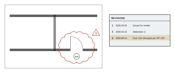
Practices vary: some designers keep all previous clouds on the sheet, while others show only the clouds for the latest revision. Either way, the reader should compare the new sheet with the old one, not just look at the clouds, because changes are sometimes made without being clouded. PDF comparison tools that overlay two versions and highlight differences in colour are very useful for this.
Worked problem
Is this sheet current?
A superintendent on site is about to lay out partitions from a printed sheet A-201 whose revision block shows revision 2, dated three months ago. The online drawing log shows A-201 at revision 4, issued last week, with the description "Partitions revised at rooms 210 to 214 per owner request; RFI 031 response incorporated". What should the superintendent do?
Show solution
- Stop: the printed sheet is two revisions behind and the changes affect partitions, exactly the work about to start.
- Download or open revision 4 and compare it with revision 2, using clouds and an overlay comparison to find every change.
- Check whether any work already done from revision 2 is affected, and record it.
- Remove the superseded print from use, or mark it "superseded", and remind the team where the current set lives.
- If revision 4 creates new questions, for example a partition that no longer lines up with a ceiling grid or a door that conflicts with a column, issue an RFI before laying out that area.
Answer: Do not build from the outdated print. Use revision 4, compare it with the earlier version, deal with any affected work, and retire the old sheet. Building from superseded drawings is one of the most common and costly errors in construction.
Documents that change the drawings
Drawings change through several kinds of documents, each with a different contractual meaning:
- Addenda, issued during the tender or bid period, change the bid documents before contracts are signed. Bidders must acknowledge them on the bid form, and they become part of the contract.
- Instructions from the consultant during construction clarify or make minor changes that do not affect price or time.
- Change directives order changes before the price and time adjustments are agreed, so that work can proceed.
- Change orders formally amend the contract with agreed changes to scope, price and time.
- Responses to RFIs clarify the documents and sometimes lead to instructions or changes.
Under CCDC 2, the consultant issues Supplemental Instructions for minor changes that do not change price or time; a Change Directive instructs a change before the adjustment is agreed; and a Change Order records the agreed change to contract price and time.
Each of these may come with revised drawings, sketches (often numbered SK-1, SK-2) or written descriptions. Until revised sheets are issued, field staff must know which sketches and instructions modify which sheets. Many contractors mark the affected sheets with references, for example writing "See SI-014" in a cloud on the field set, or adding a digital markup hyperlinked to the instruction.
Requests for information
An RFI is a formal written question from the contractor to the designer, asking for clarification of the documents, missing information or resolution of a conflict. RFIs are normal on every project; the goal is not to avoid them but to ask good ones early. A good RFI:
- Asks one clear question about one issue.
- Identifies the exact location by grid, level and room, and the relevant sheets, details and specification sections.
- Explains the problem with facts: what the documents say, why it does not work, and any measurements or photos.
- Proposes a solution when the contractor has one, so the designer can simply accept it, while recognizing that the design decision remains the designer's.
- States when an answer is needed to avoid delay, and notes possible cost or schedule impacts.
Worked problem
Checking a ceiling space before writing an RFI
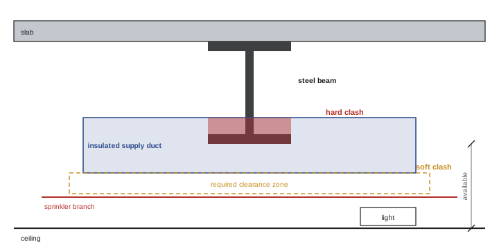
In corridor 210, the architectural drawings show a ceiling at 2 600 mm above a floor at elevation 104.200. The structural drawings show a W460×60 beam (about 455 mm deep) crossing the corridor with its top of steel at 107.800. The mechanical drawings show a 600 × 400 supply duct running along the corridor under the beam, with 25 mm of insulation and about 50 mm needed for hangers and clearance, and a 300 mm deep light fixture and sprinkler zone needed above the ceiling. Is there enough space?
Show solution
- Underside of beam: 107.800 − 0.455 = 107.345.
- Ceiling elevation: 104.200 + 2.600 = 106.800.
- Space between ceiling and beam: 107.345 − 106.800 = 0.545 m = 545 mm.
- Space needed: duct 400 + insulation 2 × 25 + hangers and clearance 50 + fixture and sprinkler zone 300 = 800 mm.
- Shortfall: 800 − 545 = 255 mm. The duct cannot run under the beam as drawn.
Answer: There is about 545 mm of space but about 800 mm is needed, a shortfall of about 255 mm. This is a clear RFI: describe the conflict at the beam location with sheet references and suggest options, such as a flatter, wider duct (for example 1 000 × 250), rerouting, a local bulkhead or a lowered ceiling, for the engineers and architect to decide.
Before writing any RFI, check that the answer is not already in the documents: the specifications, a typical detail, a schedule or an addendum. RFIs that ask questions answered in the documents waste time and damage credibility. Track every RFI in a log with its number, date sent, date required, status and the response, and make sure answers reach the people doing the work.
Clash detection and coordination drawings
On projects with BIM, the trades' models are combined into a federated model and checked for clashes: places where two objects occupy the same space (hard clashes) or violate a required clearance (soft clashes), such as the duct and beam in the example above. Coordination meetings review clashes, assign responsibility and agree solutions, and the trades update their models until the area is clear. The result is a set of coordination drawings or models that the trades install from, often with sign-off by each trade. Without BIM, coordination is done by overlaying 2-D drawings, which is slower and misses more conflicts.
Marking up drawings
Everyone on a project marks up drawings: designers in reviews, estimators in takeoffs, superintendents for layout, trades for coordination and record keeping. Digital markups in PDF software use clouds, text boxes, callouts, measurements, highlights and stamps, and can be shared, filtered and summarized. Good markup practice includes:
- Using consistent colours with an agreed meaning, for example red for changes or deletions, blue or green for additions, and yellow for highlighting.
- Clouding every change and adding a clear note with the date, author and source (such as an RFI or instruction number).
- Never marking up the only copy of an issued drawing; working on a copy or a markup layer.
- Keeping as-built markups current as work progresses (Lesson 12).
Shop drawing review
Shop drawings, product data and samples are submitted by the contractor to the designer for review, as required by the specifications (Lesson 10). The contractor reviews them first for coordination, dimensions and conformance with the contract, then the designer reviews them for general conformance with the design intent. Review stamps typically have options such as "Reviewed", "Reviewed as noted", "Revise and resubmit" and "Rejected". Review by the designer does not usually relieve the contractor of responsibility for dimensions, quantities, fabrication methods and coordination, as the stamp wording and contract make clear. Shop drawings are not contract documents, and changes shown in them are not authorized changes unless the designer issues an instruction or change.
Common mistakes
MistakeBuilding from a printed sheet without checking the current revision.
InsteadCheck the drawing log or CDE before using any sheet.
MistakeLooking only at revision clouds.
InsteadCompare the whole sheet with the previous version.
MistakeTreating the model as the contract when it is not.
InsteadUse the model for understanding; check what the contract says governs.
MistakeWriting vague RFIs or asking questions answered in the documents.
InsteadAsk one clear, referenced question with a proposed solution and a required date.
MistakeTreating changes shown on shop drawings as approved changes.
InsteadGet changes authorized through instructions or change orders.
Summary and key terms
- BIM generates drawings from an intelligent 3-D model; issued drawings usually remain the contract.
- Common formats include PDF, DWG, native BIM files, IFC (ISO 16739) and point clouds.
- LOD describes how complete and reliable model elements are.
- Common data environments manage versions; always use the current sheet.
- Revisions are marked with clouds, deltas and revision block entries.
- Addenda, instructions, change directives and change orders change the documents.
- Good RFIs are specific, referenced, timely and propose solutions.
- BIM
- Building information modelling: designing with intelligent 3-D objects.
- IFC
- Open standard (ISO 16739) for exchanging BIM data.
- Level of development
- Completeness and reliability of a model element.
- BIM execution plan
- Agreement on model uses, responsibilities and deliverables.
- Common data environment
- Shared platform managing project information and versions.
- Revision cloud
- Scalloped outline around changed work.
- Addendum
- Change to bid documents issued before contract award.
- RFI
- Request for information: a formal question to the designer.
- Clash detection
- Finding conflicts between elements in a federated model.
- Shop drawing review
- Designer's check of submittals for general conformance.
Practice problems
Work each problem on paper first, then reveal the answer to check.
What is the main advantage of BIM over 2-D CAD for drawing consistency?
Show answer
Views and schedules update from one model.
What does IFC stand for, and why is it useful?
Show answer
Industry Foundation Classes; an open, vendor-neutral exchange format.
What LOD is usually needed for trade coordination?
Show answer
LOD 300 to 350.
Name the three ways a revision is identified on a sheet.
Show answer
Cloud, delta, revision block entry.
What is the difference between an addendum and a change order?
Show answer
Addenda come before award; change orders amend the signed contract.
List four elements of a good RFI.
Show answer
One question, location and references, facts, proposed solution, required date.
Underside of beam 107.200, ceiling 106.650. Space?
Show answer
550 mm.
What is a soft clash?
Show answer
A violation of a required clearance.
Does designer review of shop drawings relieve the contractor of dimension responsibility?
Show answer
Usually not.
What should you do with superseded printed sheets?
Show answer
Remove them or mark them superseded.
Lesson quiz · 5 questions
Score 60% or more to complete this lesson.
Create a free account to save your progress, take quizzes and earn a certificate.