
CIV-470 · Lesson 4 of 12 · 19 min
Urban drainage: inlets and storm sewers
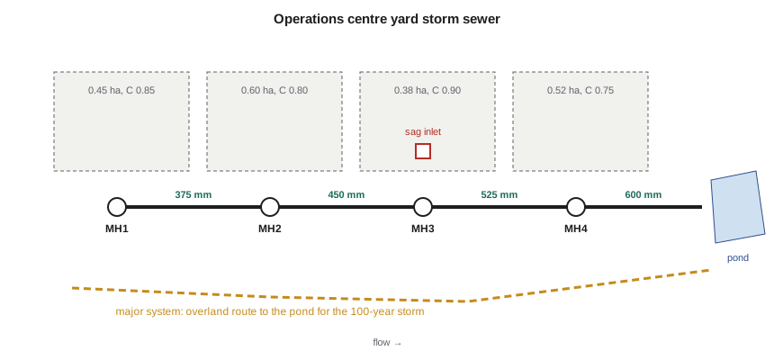
Phase 3 of the operations centre adds a fleet yard, a salt shed apron and staff parking, and most of the new paved area drains to a storm sewer that discharges to the stormwater pond designed in CIV-370. Owen's task is to lay out and size that sewer: where the inlets go, how large each pipe must be, and how the system behaves when a storm bigger than its design arrives. Urban drainage design has its own vocabulary and its own simplifications, and this lesson works through them on the yard sewer.
The minor and major systems
Urban drainage has two parts. The minor system, made up of gutters, inlets, catch basins, storm sewers and ditches, carries frequent storms, so that streets, parking and yards stay usable. The major system carries the runoff that exceeds the minor system in rare storms: overland flow routes along streets, swales and channels, and the ponds that receive them. The major system is always there, whether designed or not; good design makes sure its paths lead to safe outlets and do not cross buildings.
Ontario municipalities typically size the minor system for a storm with a return period of 2 to 10 years and the major system for the 100-year storm or the regional storm, following the provincial stormwater manual and their own design standards. The City of Thunder Bay standard used here is a 5-year minor system, with the 100-year flow carried overland to the pond without flooding buildings and with limits on the depth of water on roads.
Gutters and inlets
Water collects first in gutters and shallow channels. Gutter capacity is calculated from a form of Manning's equation for a triangular section, and design limits the spread of water into the travel lane or the depth at low points. Inlets intercept the gutter flow. Grate inlets set in the gutter are efficient where flow is fast and debris is light; curb-opening inlets, slots in the curb face, are less efficient on grade but resist clogging; combination inlets join both. Inlets on a continuous grade let some flow pass by to the next inlet, and their efficiency falls as the flow increases. Inlets in a sag, a low point, must take all the flow, because anything they miss ponds until it can overflow somewhere else.
A grate in a sag works as a weir at shallow depth, with the flow spilling over its perimeter, and as an orifice when the water is deep enough to submerge it. Its capacity is the smaller of the two:
with \(C_w = 1.66\), \(C_o = 0.67\), the perimeter \(P\), the open area \(A_o\) and the depth \(d\). Debris is the enemy of sag inlets: leaves, ice and litter can block half the grate, and designers commonly halve the perimeter and open area to allow for clogging, or provide a second inlet or an overflow path at every sag.
The rational method for storm sewers
Storm sewers for small catchments are sized with the rational method from CIV-370, applied pipe by pipe. At each pipe the design flow is computed from the sum of the runoff coefficients times areas upstream, \(\sum CA\), and the rainfall intensity for a duration equal to the time of concentration at that point:
The time of concentration grows downstream: it starts as the inlet time, the time for water to flow over the surface to the first inlet, typically 5 to 15 minutes for paved areas, and increases by the travel time in each pipe. Because intensity falls as duration increases, the flow downstream grows more slowly than the area. Each pipe is then chosen as the smallest standard size whose full-flow capacity by Manning's equation exceeds the design flow:
and the travel time in that pipe is its length divided by the full-flow velocity, a convenient approximation. Design standards also set a minimum velocity, about 0.6 to 0.9 m/s when flowing full, so that sediment does not settle, and a maximum velocity to limit abrasion. Pipes do not decrease in size downstream, and crowns of pipes entering a manhole are usually matched so that the larger outgoing pipe does not back water into the smaller ones.
# Storm sewer design for the operations site yard: rational method, Manning pipes, sag inlet
from math import pi, sqrt
UNITS = "SI"
SI = UNITS == "SI"
n = 0.013
idf = lambda t: 0.58 * 1340 / (t + 6) ** 0.8          # 5-year intensity, mm/h (illustrative IDF from CIV-370)
sizes = [0.300, 0.375, 0.450, 0.525, 0.600, 0.675, 0.750] if SI else [12, 15, 18, 21, 24, 27, 30]
# reach: (name, area ha, C, length m, slope)
reaches = [("MH1-MH2", 0.45, 0.85, 85, 0.006), ("MH2-MH3", 0.60, 0.80, 110, 0.005),
           ("MH3-MH4", 0.38, 0.90, 95, 0.005), ("MH4-outfall", 0.52, 0.75, 120, 0.004)]
def qfull(D, S):                                      # D in m, Q in m3/s
    A = pi * D * D / 4; R = D / 4
    return A * R ** (2 / 3) * S ** 0.5 / n, (R ** (2 / 3) * S ** 0.5 / n)
sumCA, tc = 0.0, 10.0
print("reach        sum CA   tc    i      Q      pipe    Qfull   Vfull  t_travel" if SI else
      "reach        sum CA   tc    i      Q      pipe    Qfull   Vfull  t_travel")
for name, a, c, Lr, S in reaches:
    sumCA += a * c
    i = idf(tc)
    Q = sumCA * i / 360                              # Q = CiA/360 with A in ha, i in mm/h
    for Dsz in sizes:
        D = Dsz if SI else Dsz * 0.0254
        Qf, Vf = qfull(D, S)
        if Qf >= Q: break
    tt = Lr / Vf / 60
    if SI:
        print(f"{name:11s} {sumCA:5.3f} ha {tc:5.1f} {i:5.1f}  {Q*1000:4.0f} L/s  {Dsz*1000:3.0f} mm  {Qf*1000:4.0f}  {Vf:4.2f} m/s  {tt:4.1f} min")
    else:
        print(f"{name:11s} {sumCA*2.471:5.2f} ac {tc:5.1f} {i/25.4:5.2f}  {Q*35.315:5.1f} cfs  {Dsz:2d} in.  {Qf*35.315:5.1f}  {Vf/0.3048:4.2f} ft/s  {tt:4.1f} min")
    tc += tt
# sag inlet: a grate in a low point, checked as a weir and as an orifice with 50 % clogging
g = 9.81
side, d = 0.60, 0.15                       # grate side, allowed ponding depth (m)
P = 4 * side * 0.5                         # clogged perimeter
Aopen = side * side * 0.5 * 0.5            # half the area is open, half of that clogged
qweir = 1.66 * P * d ** 1.5
qorif = 0.67 * Aopen * sqrt(2 * g * d)
cap = min(qweir, qorif)
if SI:
    print(f"\nSag grate {side:.2f} x {side:.2f} m at {d:.2f} m depth: weir {qweir*1000:.0f} L/s, orifice {qorif*1000:.0f} L/s -> capacity {cap*1000:.0f} L/s")
else:
    print(f"\nSag grate 24 x 24 in. at 6 in. depth: weir {qweir*35.315:.2f} cfs, orifice {qorif*35.315:.2f} cfs -> capacity {cap*35.315:.2f} cfs")
q_gutter = 0.38 * 0.85 * idf(10) / 360
print(f"Flow reaching the MH3 low point: {q_gutter*1000:.0f} L/s -> {'one grate is enough' if q_gutter <= cap else 'two grates needed'}" if SI else
f"Flow reaching the MH3 low point: {q_gutter*35.315:.2f} cfs -> {'one grate is enough' if q_gutter <= cap else 'two grates needed'}")reach sum CA tc i Q pipe Qfull Vfull t_travel MH1-MH2 0.383 ha 10.0 84.6 90 L/s 375 mm 136 1.23 m/s 1.2 min MH2-MH3 0.863 ha 11.2 80.0 192 L/s 450 mm 202 1.27 m/s 1.4 min MH3-MH4 1.205 ha 12.6 75.0 251 L/s 525 mm 304 1.40 m/s 1.1 min MH4-outfall 1.595 ha 13.7 71.5 317 L/s 600 mm 388 1.37 m/s 1.5 min Sag grate 0.60 x 0.60 m at 0.15 m depth: weir 116 L/s, orifice 103 L/s -> capacity 103 L/s Flow reaching the MH3 low point: 76 L/s -> one grate is enough
Reading the results
The design sheet builds the time of concentration from 10 minutes at MH1 to 13.7 minutes at the outfall, and the 5-year intensity falls from 84.6 to 71.5 mm/h as it does. The pipes step up from 375 mm to 600 mm, each with a full-flow velocity of 1.2 to 1.4 m/s, comfortably above the self-cleansing minimum. The outfall pipe carries 317 L/s against a full capacity of 388 L/s. The sag grate at MH3 has a clogged capacity of 103 L/s, controlled by orifice flow at the 0.15 m allowed depth, against 76 L/s arriving from its sub-catchment, so one grate is enough, but the team adds an overflow swale to the pond in case it blocks completely.
Worked problem
Sizing the first pipe by hand
The first sub-catchment is 0.45 ha with \(C = 0.85\), the inlet time is 10 min and the 5-year IDF is \(i = 0.58 \times 1340/(t+6)^{0.8}\) mm/h. The pipe from MH1 to MH2 is 85 m long at 0.6 % with \(n = 0.013\). Size it.
Show solution
- \[i = \frac{0.58 \times 1340}{(10 + 6)^{0.8}} = \frac{777}{9.19} = 84.6\ \text{mm/h}\]
- \[Q = \frac{84.6 \times 0.85 \times 0.45}{360} = 0.090\ \text{m}^3/\text{s}\]
- Try 300 mm: \(A = 0.0707\), \(R = 0.075\), \(Q_{\text{full}} = (1/0.013)(0.0707)(0.075)^{2/3}(0.006)^{1/2} = 0.075\) m³/s, too small.
- Try 375 mm: \(A = 0.110\), \(R = 0.094\), \(Q_{\text{full}} = 0.136\) m³/s, \(V = 1.23\) m/s. Use 375 mm.
- Travel time \(85/1.23 = 69\) s \(= 1.2\) min, so the time of concentration at MH2 is 11.2 min.
Answer: A 375 mm pipe carries the 90 L/s with spare capacity; the next reach uses the new time of concentration of 11.2 min.
The hydraulic grade line
Pipes sized for full flow at their slope are only the first step. During the design storm, and especially in larger storms, the water surface in the system, the hydraulic grade line, may rise above the pipe crowns if the outlet is submerged or if losses at manholes, bends and junctions are large. The hydraulic grade line is computed upstream from the outlet, starting from the tailwater level, here the pond's water level, and adding friction losses in each pipe and minor losses at each structure, typically a coefficient times the velocity head \(K V^2/2g\). The grade line must stay below the rims of catch basins and manholes, with a margin, and well below basement floors in areas with building connections.
For the yard sewer the pond's 5-year water level is about 0.6 m above the outfall invert, so the outfall pipe flows partly submerged. Owen's hydraulic grade line check shows the water surface at MH4 sits 0.4 m above the pipe crown but 1.1 m below the rim, which is acceptable. In the 100-year storm, the sewer surcharges, the excess flows overland along the designed route, and the grade line at MH3 rises to 0.2 m below the rim, which the team also accepts because there are no buildings connected to the yard sewer.
| Reach | Design flow (L/s) | Pipe (mm) | Full velocity (m/s) |
|---|---|---|---|
| MH1–MH2 | 90 | 375 | 1.23 |
| MH2–MH3 | 192 | 450 | 1.27 |
| MH3–MH4 | 251 | 525 | 1.40 |
| MH4–outfall | 317 | 600 | 1.37 |
Beyond the rational method
The rational method is accepted for small systems, usually up to a few tens of hectares, where the peak flow is all that matters. Larger systems, systems with storage or surcharging, and systems that must be checked for the major storm are modelled with dynamic hydraulic models such as EPA's Storm Water Management Model (SWMM) and commercial packages based on it. These route hydrographs through the pipe network with the full equations of unsteady flow, represent surcharge, backwater and overland flow, and are calibrated against flow monitoring. The yard sewer is simple enough for a design sheet, but the master plan's model of the whole operations centre, including the pond and the creek outlet, is built in SWMM.
Practical points
- Design the minor system for frequent storms and make sure a safe major-system route exists for rare ones.
- Build the time of concentration downstream: inlet time plus pipe travel times.
- Allow for clogging at sag inlets, and provide an overflow path at every sag.
- Check the hydraulic grade line from the outlet tailwater upward, including manhole losses.
- Never let pipe sizes decrease downstream, and match crowns at manholes.
Common mistakes
MistakeUsing the same intensity for every pipe in a system.
InsteadUse the intensity for the time of concentration at each point; it decreases downstream.
MistakeSizing pipes for full flow and stopping there.
InsteadCheck the hydraulic grade line with the tailwater and structure losses.
MistakeTreating a sag inlet like an inlet on grade.
InsteadIn a sag all the flow must enter or pond; allow for clogging.
MistakeIgnoring the major system because the sewer is sized for the 5-year storm.
InsteadLarger storms still arrive; plan the overland routes and ponding.
Summary and key terms
- Urban drainage has a minor system for frequent storms and a major system of overland routes and ponds for rare ones.
- Inlets on grade pass some flow; sag inlets must take it all and are sized as weirs or orifices with a clogging allowance.
- Storm sewers are sized pipe by pipe with the rational method, using the time of concentration at each point.
- Manning's full-flow capacity selects the pipe size, with minimum velocities for self-cleansing.
- The yard sewer steps from 375 to 600 mm and carries 317 L/s at the outfall in the 5-year storm.
- The hydraulic grade line must stay below rims and basements; dynamic models handle complex systems.
- Minor system
- Gutters, inlets, sewers and ditches designed for frequent storms.
- Major system
- Overland flow routes and ponds that carry runoff exceeding the minor system.
- Sag inlet
- An inlet at a low point, which must capture all the flow reaching it.
- Inlet time
- The time for runoff to travel over the surface to the first inlet.
- Time of concentration
- The time for runoff from the most remote point to reach the point of interest.
- Hydraulic grade line
- The line of the water surface, or of the pressure head in a full pipe, along a drainage system.
- Surcharge
- Flow in a sewer under pressure, with the hydraulic grade line above the pipe crown.
- Crown matching
- Setting pipes so that their tops align at a manhole, preventing backwater into smaller upstream pipes.
Practice problems
Work each problem on paper first, then reveal the answer to check.
A catchment of 0.80 ha with \(C = 0.75\) has a time of concentration of 15 min, where the intensity is 70 mm/h. Find the design flow.
Show answer
\(Q = 70 \times 0.75 \times 0.80/360 = 0.117\) m³/s.
Find the full-flow capacity of a 450 mm pipe at 0.5 % with \(n = 0.013\).
Show answer
\(A = 0.159\), \(R = 0.1125\); \(Q = 0.202\) m³/s.
A sag grate has a clogged perimeter of 1.2 m. Find its weir capacity at a depth of 0.15 m.
Show answer
\(Q = 1.66(1.2)(0.15)^{1.5} = 0.116\) m³/s.
Why does the design flow in a storm sewer grow more slowly than the drainage area downstream?
Show answer
The time of concentration increases, so the design intensity decreases as the area increases.
Lesson quiz · 5 questions
Score 60% or more to complete this lesson.
Create a free account to save your progress, take quizzes and earn a certificate.