
CIV-330 · Lesson 9 of 12 · 22 min
Two-way slabs and the direct design method
When a slab panel is close to square and supported on all four sides, or sits directly on columns without beams, it bends in two directions at once. Two-way slabs are the most common floor system in concrete office buildings, apartments and hospitals because they give flat ceilings, low floor-to-floor heights and simple formwork. This lesson introduces the types of two-way systems, their thickness, the direct design method for finding moments, and the punching shear check that usually decides the thickness of a flat plate. The example is the administration wing of the operations centre.
Two-way systems
- Flat plate: a slab of uniform thickness supported directly on columns. It is the cheapest to form and gives the thinnest floor, but punching shear around the columns limits spans to about 7 to 9 m (25 to 30 ft) for ordinary loads.
- Flat slab: a flat plate thickened around the columns by drop panels or column capitals, which increase punching shear strength and negative moment capacity. It suits heavier loads such as parking and storage.
- Two-way slab with beams: a slab supported on beams along all column lines. The beams stiffen the floor and carry much of the load, allowing thinner slabs, at the cost of deeper structure and more formwork.
- Waffle slab: a two-way joist system with ribs in both directions, formed with domes, for long spans and heavy loads with low self-weight.
The administration wing is a two-storey block east of the office building, where the architect wants flat ceilings with exposed services and the lowest possible floor-to-floor height. The structure is a flat plate on a 7.5 m × 7.5 m column grid, with 500 × 500 mm columns and a perimeter spandrel beam that also carries the exterior cladding.
How two-way slabs carry load
Picture the load on a flat plate panel flowing first in one direction to the column lines, and then along the column lines to the columns. Every bit of load must travel both ways: the total moment in each direction must equal the full static moment of the panel, not half of it. This surprises many students, but it follows directly from equilibrium of a panel cut out along the column lines and the panel centrelines.
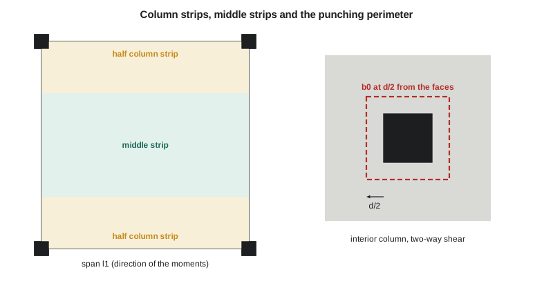
Along each column line the slab is stiffer and more heavily stressed than midway between columns, so moments are concentrated in a column strip, centred on the column line, and smaller in the middle strip between. The codes define the column strip width on each side of the column line as a quarter of the shorter panel dimension, so the column strip is half the panel width in a square panel, and the middle strip is the remainder.
Minimum thickness
A23.3 sets minimum thicknesses for two-way slabs that make deflection calculations unnecessary. For a flat plate without drop panels the minimum is \(h_s \ge l_n(0.6 + f_y/1000)/30\), where \(l_n\) is the longer clear span. At discontinuous edges without an edge beam stiff enough, the thickness is increased by about 10 per cent. Drop panels allow a reduction, and slabs with stiff beams on all sides follow a separate expression.
For the administration wing, \(l_n = 7.5 - 0.5 = 7.0\) m and \(h_s \ge 7000(0.6 + 0.4)/30 = 233\) mm. The spandrel beams make the 10 per cent increase unnecessary at the edges. Owen uses 250 mm, which also gives room for two layers of 15M bars and some margin for punching shear.
The direct design method
The direct design method is a set of coefficients for regular slabs, similar in spirit to the beam coefficients of lesson 8. It applies when there are at least three continuous spans in each direction, panels are rectangular with a long-to-short ratio not more than 2, successive spans differ by no more than a third of the longer one, columns are not offset more than about a tenth of the span from the grid, loads are uniform gravity loads, and the live load is not more than twice the dead load. Irregular slabs are analysed by the equivalent frame method or by finite elements.
The method has three steps. First, the total factored static moment for a span in one direction is computed for the full width \(l_2\) of the design strip between panel centrelines:
with \(l_n\) the clear span between column faces. Second, \(M_o\) is divided between the negative moments at the supports and the positive moment at midspan. In an interior span the split is 65 per cent negative and 35 per cent positive. End spans have smaller negative moments at the exterior support, which is flexible, and larger positive and interior negative moments.
| Moment in end span | Flat plate, no edge beam | Flat plate with edge beam | Interior span |
|---|---|---|---|
| Exterior negative | 0.26 | 0.30 | — |
| Positive | 0.52 | 0.50 | 0.35 |
| Interior negative | 0.70 | 0.70 | 0.65 |
Third, each moment is divided between the column strip and the middle strip. For flat plates A23.3 allows the designer to assign the column strip a share of the interior negative moment within a range; a common choice is about three quarters. The column strip takes about 60 per cent of the positive moment and essentially all of the exterior negative moment. A23.3 also requires part of the column-strip top steel at each column to be concentrated in a band about \(c_2 + 3h_s\) wide centred on the column, where the slab is most heavily stressed and where moment is transferred to the column.
Punching shear
The critical check for a flat plate is shear around the columns. The slab can fail by punching: a truncated cone or pyramid of concrete around the column shears out, and the slab drops down around it. Punching failures are brittle and can propagate from one column to the next, producing a progressive collapse. Several parking structures and buildings have failed this way during construction, when shoring was removed too early or loads were placed on young concrete.
Two-way shear is checked on a critical perimeter at \(d/2\) from the faces of the column, where \(d\) is the average effective depth of the slab. The factored shear stress on that perimeter is compared with a concrete shear stress resistance:
where \(\beta_c\) is the ratio of long to short column side, \(b_o\) is the perimeter of the critical section and \(\alpha_s\) is 4 for interior, 3 for edge and 2 for corner columns. For square interior columns of normal size the third expression, \(0.38\lambda\phi_c\sqrt{f'_c}\), governs. For slabs with \(d\) greater than 300 mm the resistance is reduced by the factor \(1300/(1000 + d)\) to account for size effect.
When the column also transfers an unbalanced moment to the slab, as at edge columns or under unequal spans, part of the moment is transferred by eccentric shear on the critical perimeter, which raises the shear stress on one side. Edge and corner columns of flat plates are often more critical than interior ones for this reason, and designers check them with the full moment transfer analysis. If the shear stress is too high, the options are a thicker slab, drop panels, larger columns, higher-strength concrete, or shear reinforcement in the form of headed shear studs or stirrup cages.
Worked problem
Administration wing flat plate
Find the interior span moments in the column and middle strips, the column strip top steel, and check punching shear at an interior column. \(h = 250\) mm, average \(d = 209\) mm, \(f'_c = 30\) MPa, 15M bars, loads \(D = 0.25 \times 24 + 1.5 = 7.5\) kPa and \(L = 2.4\) kPa.
Show solution
- \[w_f = 1.25(7.5) + 1.5(2.4) = 12.97\ \text{kPa} \qquad M_o = \frac{12.97(7.5)(7.0)^2}{8} = 596\ \text{kN·m}\]
- Interior span: negative \(0.65M_o = 387\) kN·m, positive \(0.35M_o = 209\) kN·m.
- Column strip, 3.75 m wide: negative \(0.75(387) = 291\) kN·m, positive \(0.60(209) = 125\) kN·m. Middle strip, 3.75 m wide: negative 97 kN·m, positive 83 kN·m.
- Column strip top steel from the flexure quadratic: \(A_s = 4350\) mm², i.e. 15M at \(200(3750)/4350 = 172\), use 15M at 170 mm. All other strips need only the minimum \(0.002(250)(3750) = 1875\) mm², 15M at 400 mm, with spacing not more than \(2h = 500\) mm.
- Punching at an interior column:
- \[b_o = 4(500 + 209) = 2836\ \text{mm} \qquad V_f = 12.97\Big(7.5^2 - 0.709^2\Big) = 723\ \text{kN}\]
- \[v_f = \frac{723\,000}{2836(209)} = 1.22\ \text{MPa}\]
- \[v_c = 0.38(1.0)(0.65)\sqrt{30} = 1.35\ \text{MPa} \quad (\text{the other two expressions give 2.03 and 1.73 MPa})\]
Answer: The interior column passes punching with \(v_f/v_c = 0.90\). The column strip needs 15M at 170 mm top; the rest of the slab takes minimum steel. Edge columns will need a moment transfer check and may need headed studs.
import math
# Administration wing flat plate, CSA A23.3: thickness, direct design moments, punching shear
fc, fy, phic, phis = 30.0, 400.0, 0.65, 0.85
l1 = l2 = 7.5; c = 0.5                                   # m
ln = l1 - c
h_min = ln * 1000 * (0.6 + fy / 1000) / 30
print(f"minimum thickness, interior panel: {h_min:.0f} mm; about 10% more at edges without beams: {1.1*h_min:.0f} mm")
h = 250.0
d = h - 25 - 16                                          # average d for two layers of 15M
wf = 1.25 * (h / 1000 * 24 + 1.5) + 1.5 * 2.4            # kPa
Mo = wf * l2 * ln**2 / 8
print(f"h = {h:.0f} mm, d = {d:.0f} mm, wf = {wf:.2f} kPa, Mo = {Mo:.0f} kN.m")

neg, pos = 0.65 * Mo, 0.35 * Mo                          # interior span
cs_neg, cs_pos = 0.75, 0.60                              # column strip shares used here
a1 = 0.85 - 0.0015 * fc
def As(Mf, b):
    k = (phis * fy) ** 2 / (2 * a1 * phic * fc * b)
    return (phis * fy * d - math.sqrt((phis * fy * d) ** 2 - 4 * k * Mf * 1e6)) / (2 * k)
cs_w = min(l1, l2) / 2 * 1000                            # column strip width, mm
ms_w = l2 * 1000 - cs_w
for label, M, share in (("negative", neg, cs_neg), ("positive", pos, cs_pos)):
    Mc, Mm = share * M, (1 - share) * M
    Ac = max(As(Mc, cs_w), 0.002 * h * cs_w)            # minimum 0.002Ag in each strip
    Am = max(As(Mm, ms_w), 0.002 * h * ms_w)
    sc, sm = min(200 * cs_w / Ac, 2 * h), min(200 * ms_w / Am, 2 * h)
    print(f"{label}: total {M:.0f}, column strip {Mc:.0f} kN.m -> As {Ac:.0f} mm2 (15M @ {sc:.0f}); "
          f"middle strip {Mm:.0f} kN.m -> As {Am:.0f} mm2 (15M @ {sm:.0f})")

# Two-way (punching) shear at an interior column, critical section d/2 from the faces
b0 = 4 * (c * 1000 + d)
Vf = wf * (l1 * l2 - ((c * 1000 + d) / 1000) ** 2)
vf = Vf * 1000 / (b0 * d)
rt = math.sqrt(fc); bc, als = 1.0, 4
vc = min((1 + 2 / bc) * 0.19 * phic * rt, (als * d / b0 + 0.19) * phic * rt, 0.38 * phic * rt)
if d > 300: vc *= 1300 / (1000 + d)
print(f"punching: b0 = {b0:.0f} mm, Vf = {Vf:.0f} kN, vf = {vf:.2f} MPa, vc = {vc:.2f} MPa "
f"-> {'OK' if vf <= vc else 'needs shear reinforcement or a drop panel'}")minimum thickness, interior panel: 233 mm; about 10% more at edges without beams: 257 mm h = 250 mm, d = 209 mm, wf = 12.97 kPa, Mo = 596 kN.m negative: total 387, column strip 291 kN.m -> As 4351 mm2 (15M @ 172); middle strip 97 kN.m -> As 1875 mm2 (15M @ 400) positive: total 209, column strip 125 kN.m -> As 1875 mm2 (15M @ 400); middle strip 83 kN.m -> As 1875 mm2 (15M @ 400) punching: b0 = 2836 mm, Vf = 723 kN, vf = 1.22 MPa, vc = 1.35 MPa -> OK
The program makes it easy to see how sensitive the punching check is. Sofia tries a 7.5 per cent increase in the live load for a future records room and the ratio rises above 0.95; she tries a 50 mm (2 in.) larger column and it falls to 0.84. Thickness, column size and concrete strength are all effective, and the team keeps all three options open until the architect fixes the column sizes.
Integrity reinforcement and detailing
Because punching can trigger a progressive collapse, A23.3 requires structural integrity reinforcement: bottom bars passing continuously through each column in both directions, with an area sufficient to hang the slab from the column after a punching failure. The required area is \(\sum A_{sb} = 2V_{se}/f_y\), where \(V_{se}\) is the shear from specified loads. These bars act as a catenary net that keeps the slab from falling if the concrete around the column fails.
Other detailing rules for two-way slabs include minimum bar extensions (top bars in column strips typically extend 0.30\(l_n\) past the face of the support, and middle strip top bars about 0.22\(l_n\)), corner reinforcement in slabs with stiff edge beams, limits on openings near columns (which reduce the critical perimeter), and careful placing of the top bars, whose effective depth is easily lost if the bars are walked down during the pour.
Other analysis methods
- Equivalent frame method: the slab and columns along each column line are modelled as a plane frame with special stiffnesses for the slab-column connection. It handles irregular spans and lateral loads.
- Finite element analysis: plate elements give moment contours directly, which are integrated over strip widths to obtain design moments. It is now routine in design offices but needs judgement in modelling cracking, supports and load patterns.
- Yield line analysis: an upper-bound plastic method that gives the collapse load of a slab with a chosen pattern of hinge lines. It is useful for checking existing slabs and unusual shapes.
- Strip method: a lower-bound method that assigns load paths to strips in each direction, convenient for slabs with openings.
Common mistakes
MistakeDesigning each direction of a two-way slab for half the load.
InsteadEquilibrium requires the full static moment \(M_o\) in each direction.
MistakeChecking punching shear at the column face.
InsteadThe critical perimeter is at \(d/2\) from the faces, using the average effective depth.
MistakeIgnoring moment transfer at edge columns.
InsteadUnbalanced moment adds eccentric shear on one side of the perimeter; edge columns often govern.
MistakeOmitting integrity bars because the punching check passes.
InsteadIntegrity reinforcement is required regardless of the calculated shear capacity.
Summary and key terms
- Two-way systems include flat plates, flat slabs with drop panels, slabs with beams and waffle slabs.
- The full static moment \(M_o = wl_2l_n^2/8\) must be resisted in each direction.
- The direct design method splits \(M_o\) into negative and positive moments (0.65/0.35 for interior spans) and then into column and middle strips.
- Minimum flat plate thickness is \(l_n(0.6 + f_y/1000)/30\); the administration wing uses 250 mm.
- Punching shear is checked at \(d/2\) with \(v_c\) typically \(0.38\lambda\phi_c\sqrt{f'_c}\), reduced for \(d > 300\) mm.
- Integrity bottom bars through the columns protect against progressive collapse after a punching failure.
- Two-way slab
- A slab that bends in two directions to supports on all sides or to columns.
- Flat plate
- A two-way slab of uniform thickness supported directly on columns.
- Drop panel
- A thickened part of a slab around a column that increases shear and moment capacity.
- Column strip
- The slab strip along a column line, a quarter of the shorter span wide on each side of the line.
- Middle strip
- The slab strip between two column strips.
- Total static moment
- The sum of positive and average negative moment in a span, Mo = wl2ln²/8.
- Punching shear
- Two-way shear failure of a slab around a column or concentrated load.
- Integrity reinforcement
- Continuous bottom bars through columns that hold the slab up after a punching failure.
Practice problems
Work each problem on paper first, then reveal the answer to check.
Find \(M_o\) for a 6.0 m × 6.0 m panel, 400 mm columns, \(w_f = 11\) kPa.
Show answer
\(l_n = 5.6\) m; \(M_o = 11(6.0)(5.6)^2/8 = 259\) kN·m.
In an interior span, how much of \(M_o\) goes to the column strip negative moment if the column strip takes 75 per cent?
Show answer
\(0.75 \times 0.65 = 0.49M_o\).
What is the minimum thickness of a flat plate with \(l_n = 6.0\) m and grade 400 steel?
Show answer
\(6000(1.0)/30 = 200\) mm.
Why are edge columns often more critical in punching than interior columns?
Show answer
They have a shorter perimeter and transfer large unbalanced moments, which add eccentric shear stress.
Name three ways to increase punching shear capacity.
Show answer
Thicker slab or drop panels, larger columns, higher-strength concrete, or shear studs.
Lesson quiz · 5 questions
Score 60% or more to complete this lesson.
Create a free account to save your progress, take quizzes and earn a certificate.