
CIV-330 · Lesson 8 of 12 · 20 min
One-way slabs
Slabs make up most of the concrete in a building. A slab supported on two opposite sides, or on beams much farther apart in one direction than the other, bends mainly in one direction and is called a one-way slab. It is designed as a series of wide, shallow beams. This lesson covers the analysis of continuous one-way slabs by moment coefficients, the design of a one-metre or one-foot strip, and the detailing rules that make slabs durable, with the garage parking level as the example.
One-way and two-way action
A rectangular panel supported on all four edges bends in both directions, but the load goes mostly to the closer supports, because a shorter span is much stiffer. For a panel whose long side is more than about twice its short side, nearly all the load is carried in the short direction, and the panel can be designed as one-way. Panels closer to square are two-way slabs, covered in lesson 9.
The upper parking level of the garage is a 200 mm slab spanning between beams at 6.0 m centres. The beams span 9.0 m between the garage frames, so each panel is 9.0 m by 6.0 m, a ratio of 1.5. Strictly that is two-way, but because the frames themselves are stiffer than the slab and the beams carry the slab load to them, the team designs the slab one-way between the beams, the common practice for beam-and-slab parking floors, and adds the minimum steel in the long direction.
A one-way slab is designed by taking a strip one unit wide, spanning between the supports, and treating it as a rectangular beam of that width. Because the slab is continuous over many beams, the strip is a continuous beam with many spans.
Thickness
Slab thickness is usually set by deflection, by fire resistance, or by cover requirements in exposed slabs. The span-to-depth limits of lesson 5 give \(l_n/20\) for simple spans, \(l_n/24\) for one end continuous and \(l_n/28\) for both ends continuous. For the garage, with a clear span of 6.0 − 0.45 = 5.55 m (the team rounds to 5.6 m), \(l_n/28 = 200\) mm for interior spans and \(l_n/24 = 233\) mm for end spans. Owen uses 200 mm throughout and checks the end span deflection by calculation, because the larger 60 mm top cover of a parking slab reduces the effective depth.
Fire resistance ratings in the building code require minimum slab thicknesses (about 100 to 150 mm, or 4 to 6 in., for one to two hours depending on aggregate type) and minimum cover to the bottom bars. In practice most floor slabs in buildings are 150 to 250 mm (6 to 10 in.) thick.
Moments and shears by coefficients
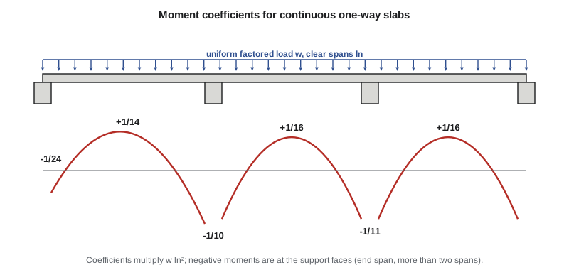
For continuous beams and one-way slabs that meet certain conditions, A23.3 permits moments and shears from tabulated coefficients instead of a full analysis. The conditions are that there are two or more spans, adjacent spans differ by no more than 20 per cent, the loads are uniformly distributed, the live load is not large compared with the dead load, and the members are prismatic. The coefficients approximate the envelope of moments from patterned live loads.
| Location | Moment | Shear |
|---|---|---|
| End span, positive (discontinuous end integral with support) | \(w l_n^2/14\) | |
| End span, positive (discontinuous end unrestrained) | \(w l_n^2/11\) | |
| Interior spans, positive | \(w l_n^2/16\) | |
| Interior face of exterior support, support is a beam | \(-w l_n^2/24\) | \(w l_n/2\) |
| Interior face of exterior support, support is a column | \(-w l_n^2/16\) | \(w l_n/2\) |
| Exterior face of first interior support, two spans | \(-w l_n^2/9\) | \(1.15w l_n/2\) |
| Exterior face of first interior support, more than two spans | \(-w l_n^2/10\) | \(1.15w l_n/2\) |
| Faces of other interior supports | \(-w l_n^2/11\) | \(w l_n/2\) |
| All supports of slabs with spans not exceeding 3 m (10 ft) | \(-w l_n^2/12\) |
The coefficients are a little conservative compared with an elastic analysis, because each one is the worst value at that location from different live load patterns. The first interior support is the most heavily loaded location, with a negative moment about 40 per cent greater than the positive moment in an interior span. When the conditions are not met, for example with a long cantilever or very unequal spans, the slab is analysed as a continuous beam with patterned live load, using the methods of CIV-321.
Reinforcement requirements
Slabs follow their own minimum steel rules. A23.3 requires at least \(0.002A_g\) of reinforcement in each direction, which serves as both the minimum flexural steel and the shrinkage and temperature steel. In the main direction the spacing may not exceed 3 times the slab thickness or 500 mm. The shrinkage and temperature steel, perpendicular to the span, may not be spaced more than 5 times the thickness or 500 mm.
Slabs are usually reinforced with the same bar size throughout, spaced in multiples of 25 mm or 1/2 in., and with spacing rounded down. Top bars over supports are extended into the spans beyond the points of inflection, commonly to about a third of the clear span past the face of each support, unless an analysis shows they can be shorter, and at least half of the bottom bars are continued into the supports.
Shear rarely governs slabs. A slab without stirrups resists \(V_c = \phi_c\lambda\beta\sqrt{f'_c}b_wd_v\) with \(\beta = 230/(1000 + d_v)\), and its thickness is normally set by deflection long before shear matters. Stirrups are impractical in slabs thinner than about 250 mm.
Worked problem
Garage parking slab
Design the 200 mm garage slab for a 1 m strip. Clear span 5.6 m, many spans, exterior edge cast with a beam. \(f'_c = 35\) MPa, 60 mm top cover (chloride exposure), 30 mm bottom cover, 15M bars. Specified loads: self-weight \(0.2 \times 23.5 = 4.7\) kPa, services 0.5 kPa, parking live load 2.4 kPa.
Show solution
- \[w_f = 1.25(4.7 + 0.5) + 1.5(2.4) = 10.1\ \text{kPa}\]
- Effective depths: top \(d = 200 - 60 - 8 = 132\) mm; bottom \(d = 200 - 30 - 8 = 162\) mm.
- First interior support (worst case):
- \[M_f = \frac{w_f l_n^2}{10} = \frac{10.1(5.6)^2}{10} = 31.7\ \text{kN·m/m}\]
- Solving the flexure quadratic with \(b = 1000\) mm and \(d = 132\) mm gives \(A_s = 745\) mm²/m: 15M at \(200 \times 1000/745 = 268\), rounded down to 250 mm.
- End span positive: \(M_f = 10.1(5.6)^2/14 = 22.6\) kN·m/m, \(A_s = 421\) mm²/m on \(d = 162\) mm: 15M at 475 mm.
- Minimum steel: \(0.002(1000)(200) = 400\) mm²/m, i.e. 15M at 500 mm, which governs at the exterior support, in interior spans and as transverse steel. Maximum spacing \(\min(3 \times 200,\ 500) = 500\) mm.
- Shear at the first interior support: \(V_f = 1.15(10.1)(5.6)/2 = 32.5\) kN/m; \(d_v = 144\) mm, \(\beta = 0.201\), \(V_c = 111\) kN/m. Shear is not a concern.
Answer: Strength needs 15M at 250 mm over the first interior support and minimum steel almost everywhere else. Crack control, checked next, tightens the top bars further.
Crack control in an exposed slab
Parking slabs crack where the top surface is in tension over the beams, which is also where salt-laden water collects. Owen checks the crack control parameter for the top bars with \(f_s = 0.6f_y = 240\) MPa and \(d_c = 60 + 8 = 68\) mm. The effective tension area per bar is \(2d_c s\). At 250 mm spacing, \(z = 240\sqrt[3]{68 \times 2 \times 68 \times 250} = 31\,700\) N/mm, above the 30 000 N/mm interior limit, even though the covered deck is protected by a membrane. Closing the spacing to 200 mm gives \(z = 29\,500\) N/mm. The larger cover needed for durability makes cracks wider at the surface, so crack control, not strength, sets the top steel.
import math
# Garage one-way slab, CSA A23.3: moment coefficients and a 1 m design strip
fc, fy, phic, phis = 35.0, 400.0, 0.65, 0.85
h, ln = 200.0, 5.6                       # mm, clear span m (beams at 6.0 m, webs 400 mm)
wf = 1.25 * (0.2 * 23.5 + 0.5) + 1.5 * 2.4
a1 = max(0.85 - 0.0015 * fc, 0.67)
d_top, d_bot = h - 60 - 8, h - 30 - 8    # 60 mm top cover (parking exposure), 15M bars
print(f"wf = {wf:.2f} kPa, thickness check ln/28 = {ln*1000/28:.0f} mm (h = {h:.0f})")

def As_req(Mf, d, b=1000.0):
    k = (phis * fy) ** 2 / (2 * a1 * phic * fc * b)
    return (phis * fy * d - math.sqrt((phis * fy * d) ** 2 - 4 * k * Mf * 1e6)) / (2 * k)

As_min = 0.002 * 1000 * h                # also the shrinkage and temperature steel
s_lim = min(3 * h, 500)
cases = [("exterior support, interior face (top)", 1 / 24, d_top),
         ("end span midspan (bottom)",           1 / 14, d_bot),
         ("first interior support (top)",       1 / 10, d_top),
         ("interior span midspan (bottom)",      1 / 16, d_bot),
         ("other interior supports (top)",       1 / 11, d_top)]
for name, c, d in cases:
    Mf = c * wf * ln**2
    As = max(As_req(Mf, d), As_min)
    s = min(200 * 1000 / As, s_lim)
    s = 25 * math.floor(s / 25)
    print(f"{name:38s} Mf = {Mf:5.1f} kN.m/m  As = {As:4.0f} mm2/m  15M @ {s:.0f}")
print(f"shrinkage and temperature (transverse): {As_min:.0f} mm2/m, 15M @ {min(200e3/As_min, 5*h, 500):.0f} max")

# One-way shear at the first interior support, no stirrups
Vf = 1.15 * wf * ln / 2
dv = max(0.9 * d_top, 0.72 * h)
beta = 230 / (1000 + dv)
Vc = phic * beta * math.sqrt(fc) * 1000 * dv / 1000
print(f"shear: Vf = {Vf:.1f} kN/m, dv = {dv:.0f} mm, beta = {beta:.3f}, Vc = {Vc:.0f} kN/m")

# Crack control for the top bars over the supports (fs = 0.6 fy, interior limit, membrane-protected deck)
fs = 0.6 * fy
dc = 60 + 16.0 / 2
for s in (275, 250, 200):
    A = 2 * dc * s                        # effective tension area per bar in a slab
    z = fs * (dc * A) ** (1 / 3)
print(f"top 15M @ {s}: z = {z:.0f} N/mm -> {'OK' if z <= 30000 else 'too wide'}")wf = 10.10 kPa, thickness check ln/28 = 200 mm (h = 200) exterior support, interior face (top) Mf = 13.2 kN.m/m As = 400 mm2/m 15M @ 500 end span midspan (bottom) Mf = 22.6 kN.m/m As = 421 mm2/m 15M @ 475 first interior support (top) Mf = 31.7 kN.m/m As = 745 mm2/m 15M @ 250 interior span midspan (bottom) Mf = 19.8 kN.m/m As = 400 mm2/m 15M @ 500 other interior supports (top) Mf = 28.8 kN.m/m As = 674 mm2/m 15M @ 275 shrinkage and temperature (transverse): 400 mm2/m, 15M @ 500 max shear: Vf = 32.5 kN/m, dv = 144 mm, beta = 0.201, Vc = 111 kN/m top 15M @ 275: z = 32760 N/mm -> too wide top 15M @ 250: z = 31735 N/mm -> too wide top 15M @ 200: z = 29460 N/mm -> OK
| Location | Steel |
|---|---|
| Top, exterior support | 15M @ 200 (same as the interior supports, for simplicity) |
| Bottom, end span | 15M @ 450 |
| Top, first interior support | 15M @ 200 |
| Bottom, interior spans | 15M @ 500 |
| Top, other interior supports | 15M @ 200 |
| Transverse (top and bottom) | 15M @ 500 bottom, 15M @ 400 top |
Owen adds three details that the analysis does not show. Top bars over the beams extend 1.9 m (about a third of the clear span) past each face so that they cover the negative moment region with margin. Transverse top bars are added over the slab, not just at the supports, to control shrinkage cracking at the exposed surface. And a drainage slope of at least 1.5 per cent is formed into the top of the slab, because ponded water and salt are the main enemy of parking structures.
Other one-way systems
- One-way joist (ribbed) slabs use closely spaced ribs with a thin top slab, formed with reusable pans. They save concrete for longer spans and light loads; the ribs are designed as T-beams and the top slab as a short one-way slab between ribs.
- Slabs on grade, such as the garage ground floor, are supported directly on soil and are designed for wheel and rack loads, joint layout and shrinkage rather than by these methods.
- Precast hollow-core planks, with a cast-in-place topping, span one way and are common for parking levels when speed of erection matters.
- Composite steel deck slabs act one-way and are used on steel-framed floors.
Common mistakes
MistakeDesigning a one-way slab with the same steel everywhere.
InsteadMoments change sign and size along the span; use the coefficients to place top and bottom steel where it is needed.
MistakeForgetting the reduced effective depth of top bars with large cover.
InsteadTop \(d\) in a parking slab can be 20 per cent less than bottom \(d\); compute both.
MistakeUsing the beam minimum steel formula for a slab.
InsteadSlabs use \(0.002A_g\) in each direction.
MistakeStopping top bars at the theoretical inflection point.
InsteadExtend them past the inflection points to cover patterned loads and diagonal cracking.
Summary and key terms
- A slab with a long-to-short side ratio over about 2, or spanning between parallel beams, is designed one-way as a strip of unit width.
- Minimum thickness for deflection is \(l_n/20\), \(l_n/24\) or \(l_n/28\) depending on continuity.
- Moment coefficients from \(1/9\) to \(1/24\) give the envelope of moments for regular continuous slabs.
- Minimum and shrinkage steel is \(0.002A_g\); main bar spacing at most \(3h\) or 500 mm.
- Shear seldom governs slabs; crack control often governs the top steel of exposed slabs with large cover.
- The garage slab is 200 mm with 15M at 200 mm over the supports and minimum steel elsewhere.
- One-way slab
- A slab that carries load mainly in one direction to parallel supports.
- Design strip
- A slab width of one metre or one foot treated as a beam.
- Moment coefficient
- A factor that multiplies w ln² to give the design moment at a location.
- Clear span
- The distance between faces of supports.
- Shrinkage and temperature reinforcement
- Steel provided to control cracking from restrained volume changes.
- Distribution steel
- Bars perpendicular to the main steel that spread concentrated loads and control cracking.
- Joist slab
- A floor of closely spaced ribs and a thin top slab acting as T-beams.
- Pattern loading
- Arrangements of live load on selected spans that produce maximum moments.
Practice problems
Work each problem on paper first, then reveal the answer to check.
Find the minimum thickness of a one-way slab with one end continuous and \(l_n = 4.8\) m.
Show answer
\(4800/24 = 200\) mm.
What is the shrinkage steel for a 180 mm slab, and what 10M spacing provides it?
Show answer
\(0.002(1000)(180) = 360\) mm²/m; 10M at \(100 \times 1000/360 = 278\), use 275 mm.
Which location has the largest negative moment in a continuous slab of many spans?
Show answer
The exterior face of the first interior support, \(w l_n^2/10\).
For \(w_f = 12\) kPa and \(l_n = 4.0\) m, find the interior span positive moment.
Show answer
\(12(16)/16 = 12.0\) kN·m/m.
Why can large cover make crack control harder?
Show answer
Crack width at the surface grows with the distance from the bar, so thicker cover permits wider surface cracks unless the bars are closer together.
Lesson quiz · 5 questions
Score 60% or more to complete this lesson.
Create a free account to save your progress, take quizzes and earn a certificate.