
CIV-330 · Lesson 7 of 12 · 22 min
Bond, development length and splices
Every calculation so far has assumed that a bar can reach its yield stress wherever the analysis needs it. That is only true if the bar is anchored well enough in the surrounding concrete to transfer its force. A bar that pulls out, or splits the concrete around it, delivers nothing. This lesson explains how force passes between steel and concrete, how the codes turn that into development lengths, and how bars are anchored with hooks, cut off where they are no longer needed, and spliced where one bar is not long enough.
How bond works
Force passes from a deformed bar to the concrete mainly by the bearing of the ribs against the concrete between them, with a small contribution from adhesion and friction. The bearing forces are inclined outward from the bar, so they push the surrounding concrete apart like a wedge. Two kinds of bond failure result. If the cover and the spacing between bars are small, the radial pressure splits the concrete along the bar, and the cover spalls off; this splitting failure is the usual one in beams. If the bar is well confined by thick cover or stirrups, splitting is prevented and the bar eventually pulls out by shearing the concrete keys between the ribs, at a higher stress.
Bond stress is not uniform. It peaks near cracks, where the steel stress changes sharply, and is small between cracks. Design therefore works with an average bond stress over a length: the development length is the embedment needed to build the bar stress from zero to yield. Over that length the bar force \(A_b f_y\) must be resisted by an average bond stress \(u\) on the bar perimeter, so \(l_d = d_b f_y/(4u)\). Everything in the code expressions refines that simple relation.
What affects development length
The required length grows with the bar diameter and the yield strength and falls as the concrete gets stronger (bond strength varies roughly with \(\sqrt{f'_c}\)). It also depends on several conditions:
- Bar position. Concrete under a deep pour of fresh concrete bleeds, and water and air collect under horizontal bars near the top of the pour, weakening bond. Top bars, with more than 300 mm (12 in.) of fresh concrete below them, need longer development.
- Coating. Epoxy coating, used in parking structures and bridges to resist corrosion, reduces friction and adhesion and needs extra length.
- Concrete density. Lightweight aggregate concrete splits more easily.
- Bar size. Small bars develop more efficiently relative to their diameter, so codes give them a reduction.
- Cover, spacing and transverse steel. Thick cover, generous spacing and stirrups crossing the potential splitting plane all delay splitting and shorten the required length.
Development length in the code
A23.3 gives a general equation that accounts for cover and transverse steel, and a simplified one that is used for most designs when the cover and spacing meet minimum values. The simplified equation is
The coefficient 0.45 applies to bars with clear cover at least \(d_b\), clear spacing at least \(1.4d_b\) and at least minimum stirrups (or clear spacing at least \(2d_b\) in slabs and walls); for other cases it rises to 0.6. The modification factors are:
| Factor | Condition | Value |
|---|---|---|
| \(k_1\) bar location | Top bars with more than 300 mm of fresh concrete below | 1.3 |
| Other bars | 1.0 | |
| \(k_2\) coating | Epoxy-coated, cover < 3db or clear spacing < 6db | 1.5 |
| Other epoxy-coated bars | 1.2 | |
| Uncoated bars | 1.0 | |
| \(k_3\) concrete density | Low-density concrete | 1.3 |
| Semi-low-density | 1.2 | |
| Normal-density | 1.0 | |
| \(k_4\) bar size | 20M and smaller | 0.8 |
| 25M and larger | 1.0 |
For the 30 MPa office concrete and grade 400 bars, a bottom 25M bar needs \(0.45(1.0)(400/\sqrt{30})(25.2) = 828\) mm, about 33 bar diameters; a top 25M bar needs 1077 mm. Those numbers are worth remembering as a sense check: bottom bars of 20M and smaller develop in roughly 26 bar diameters and larger bars in roughly 33 at this strength.
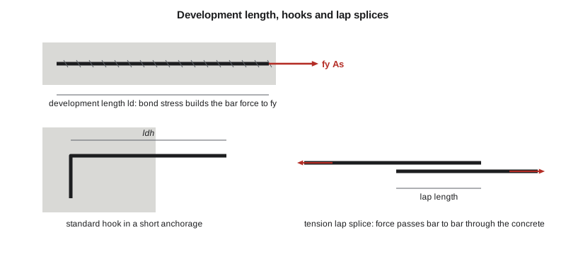
Hooks and other anchorages
Where there is not enough room for a straight bar, such as at the end of a beam framing into an exterior column, a standard hook provides anchorage in a much shorter length. The bearing of the bend on the concrete inside it carries much of the force. Standard hooks are 90 degree bends with an extension of 12 bar diameters, and 180 degree bends with an extension of 4 bar diameters, made around minimum bend diameters that avoid crushing the concrete or cracking the bar.
The basic development length of a hook in A23.3 is \(l_{hb} = 100d_b/\sqrt{f'_c}\) for grade 400 bars, scaled by \(f_y/400\) for other grades and multiplied by factors for side cover, confining ties and epoxy coating. It may not be less than \(8d_b\) or 150 mm. A 25M hook in 30 MPa concrete needs 460 mm, measured from the critical section to the outside of the bend.
Headed bars, with a forged or welded plate on the end, anchor by bearing alone and reduce congestion in beam-column joints and pile caps. Mechanical couplers join bars end to end without a lap. Both are used more and more in heavily reinforced members.
Compression development
Bars in compression develop over shorter lengths, because part of the force is transferred by end bearing and there are no flexural cracks to weaken bond. A23.3 uses \(l_{db} = 0.24f_yd_b/\sqrt{f'_c} \ge 0.044f_yd_b\), at least 200 mm. Column dowels into footings, covered in lesson 12, use this length.
Worked problem
Development lengths for the project bars
Find the development lengths for the main bars of the office beam (25M bottom, 30 MPa) and the top bars of the garage parking slab (15M, epoxy-coated, top bars, 35 MPa, cover 60 mm and spacing 250 mm).
Show solution
- Office beam bottom bars: cover and spacing meet the minimums and stirrups are present, so the 0.45 coefficient applies with all factors 1.0:
- \[l_d = 0.45(1.0)\frac{400}{\sqrt{30}}(25.2) = 828\ \text{mm}\]
- Garage slab top bars: \(k_1 = 1.3\) and \(k_4 = 0.8\). The cover of 60 mm exceeds \(3d_b = 48\) mm and the spacing of 250 mm exceeds \(6d_b = 96\) mm, so \(k_2 = 1.2\) and \(k_1k_2 = 1.56\):
- \[l_d = 0.45(1.56)(1.0)(0.8)\frac{400}{\sqrt{35}}(16.0) = 608\ \text{mm}\]
- Sofia's program uses \(k_2 = 1.5\) for every epoxy-coated bar as a conservative default; with the product capped at 1.7 it gives 662 mm, and Owen details that length.
Answer: The beam bars need 828 mm and the slab top bars about 610 to 660 mm. Both fit easily: the office beam has 3.7 m from midspan to the support, and the slab top bars extend well past the inflection points.
import math
# Development, hooks and lap splices for deformed bars, CSA A23.3 simplified equations
fy = 400.0
db = {"10M": 11.3, "15M": 16.0, "20M": 19.5, "25M": 25.2, "30M": 29.9, "35M": 35.7}

def ld(bar, fc, top=False, epoxy=False, lowdensity=False, minimum_cover=True):
    """Tension development length (mm). The 0.45 coefficient assumes clear cover and
    spacing at least db and 1.4db with minimum stirrups (or 2db spacing in slabs)."""
    k1 = 1.3 if top else 1.0
    k2 = 1.5 if epoxy else 1.0                 # 1.2 applies when cover and spacing are generous
    k3 = 1.3 if lowdensity else 1.0
    k4 = 0.8 if db[bar] <= 20 else 1.0
    coef = 0.45 if minimum_cover else 0.6
    k12 = min(k1 * k2, 1.7)                     # product of k1 and k2 need not exceed 1.7
    rt = min(math.sqrt(fc), 8.0)
    return max(coef * k12 * k3 * k4 * fy / rt * db[bar], 300.0)

def ldh(bar, fc):
    """Basic development length of a standard 90 or 180 degree hook in tension (mm)."""
    return max(100 * db[bar] / math.sqrt(fc) * fy / 400, 8 * db[bar], 150.0)

print("bar    ld bottom  ld top   ldh    lap class B")
for bar in ("15M", "20M", "25M", "30M"):
    lb = ld(bar, 30); lt = ld(bar, 30, top=True)
    print(f"{bar:4s} {lb:9.0f} {lt:8.0f} {ldh(bar, 30):6.0f} {1.3*lb:10.0f}")

# Office beam: 4-25M bottom bars, can they develop fy between midspan and the support?
L = 7500.0
avail = L / 2 - 40                         # from midspan to the bar end at the far face
print(f"office beam: 25M bottom ld = {ld('25M', 30):.0f} mm, available to midspan = {avail:.0f} mm")
# Garage slab top bars (C-1 exposure, epoxy-coated 15M top bars, f'c 35)
print(f"garage slab 15M epoxy top bars: ld = {ld('15M', 35, top=True, epoxy=True):.0f} mm")
# Compression development (column dowels)
for bar in ("20M", "25M"):
    ldc = max(0.24 * fy * db[bar] / math.sqrt(30), 0.044 * fy * db[bar], 200)
print(f"{bar} compression ld = {ldc:.0f} mm")bar ld bottom ld top ldh lap class B 15M 421 547 292 547 20M 513 666 356 666 25M 828 1077 460 1077 30M 983 1277 546 1277 office beam: 25M bottom ld = 828 mm, available to midspan = 3710 mm garage slab 15M epoxy top bars: ld = 662 mm 20M compression ld = 343 mm 25M compression ld = 444 mm
The table shows how quickly lengths grow with bar size: a top 30M bar needs nearly 1.3 m. Large top bars in thin slabs or short spans can be impossible to develop, which is one reason designers prefer more, smaller bars in slabs and why the top bars over the garage supports are 15M rather than 25M.
Cutting off bars
The moment in a beam varies along the span, so not all the bars are needed everywhere. Bars can be stopped where they are no longer required, but the rules are conservative because the moment diagram is uncertain, diagonal cracks shift the tension, and stopping bars in a tension zone creates a stress concentration that can start cracks.
- Bars are extended beyond the point where they are theoretically no longer needed by the larger of \(d\) and \(12d_b\), except at simple supports and the ends of cantilevers.
- Continuing bars must have at least a development length beyond the point where the bars that are cut off are no longer needed.
- Bars should not be cut off in a tension zone unless the shear is low or extra stirrups are added there.
- At least one third of the positive moment steel of simple spans (one quarter in continuous spans) must continue along the same face into the support.
At simple supports and inflection points, the positive moment bars must also be small enough that their development length is not more than \(M_r/V_f\) plus the embedment beyond the support or inflection point (with a 1.3 factor on \(M_r/V_f\) where the reaction confines the bar ends). This check, which comes from the rate at which bar stress must build up near a support with high shear, is what occasionally forces smaller bars or a hook at a short support.
Worked problem
Bar ends at the office beam support
Check the 4-25M bottom bars at the simple support of the office beam: \(M_r = 325\) kN·m, \(V_f = 161\) kN, bars extended 150 mm past the support centreline, with the reaction confining the ends.
Show solution
- \[1.3\frac{M_r}{V_f} + l_a = 1.3\frac{325 \times 10^6}{161 \times 10^3} + 150 = 2620 + 150 = 2770\ \text{mm}\]
- This exceeds \(l_d = 828\) mm, so the 25M bars are acceptable. All four bars continue into the support, which also satisfies the one-third rule.
Answer: No cutoff is used: in a beam this short, stopping bars saves little steel and adds detailing risk.
Splices
Bars are delivered in fixed lengths and must be joined in long members. The most common joint is a lap splice: two bars overlap and the force passes from one to the other through the concrete between them. Mechanical couplers and welded splices are used for large bars, where laps become very long and congest the section.
A23.3 classifies tension lap splices by how much of the steel is spliced at one location and how much spare capacity the bars have. A class A splice, length \(1.0l_d\), is allowed only where the steel provided is at least twice that required and no more than half the bars are spliced within the lap length. Every other tension splice is class B, length \(1.3l_d\). Splices should be staggered and located away from points of maximum stress.
Compression splices in columns are shorter, because force passes partly by end bearing, and in columns with closely spaced ties they can be shortened further. Column splices are usually located just above each floor, where the moment from lateral loads is often a maximum, which is acceptable because column bars are frequently governed by axial load.
Detailing for the operations centre
Owen prepares a bar schedule for each beam. Continuous top bars over interior supports are lapped at midspan, where the moment is positive and the top steel carries little stress. Bottom bars are lapped over the supports, where they are in compression. In the garage, epoxy-coated top bars are detailed with lengths at least 1.3 times the uncoated value, and laps of the slab top bars are staggered so that no more than half are spliced at a section.
Common mistakes
MistakeAssuming a bar is effective immediately at its end.
InsteadA bar reaches its full stress only after a development length; near its end the stress is lower.
MistakeForgetting the top bar factor for slab and beam top steel.
InsteadBars with more than 300 mm of fresh concrete below them need \(k_1 = 1.3\).
MistakeUsing a hook length measured from the end of the bar.
InsteadHook development length is measured from the critical section to the outside edge of the hook.
MistakeLapping all bars at the same section.
InsteadStagger splices; Class A splices are permitted only for lightly stressed bars with no more than half spliced.
Summary and key terms
- Deformed bars transfer force by rib bearing, which tends to split the cover; confinement by cover and stirrups resists splitting.
- Simplified A23.3: \(l_d = 0.45k_1k_2k_3k_4(f_y/\sqrt{f'_c})d_b\), about 33\(d_b\) for bottom 25M bars in 30 MPa concrete.
- Top bars, epoxy coating and lightweight concrete need longer development; small bars and confinement need less.
- Standard hooks anchor bars in short lengths; compression development is shorter than tension development.
- Cutoff rules extend bars by \(d\) or \(12d_b\), continue part of the positive steel into supports, and limit bar size at simple supports.
- Tension lap splices are Class A (\(1.0l_d\)) only in lightly stressed, staggered conditions; otherwise Class B (\(1.3l_d\)).
- Bond
- The transfer of force between reinforcing steel and the surrounding concrete.
- Development length
- The embedment length needed to develop the yield stress of a bar.
- Splitting failure
- Bond failure by cracking of the cover along a bar.
- Top bar effect
- The reduced bond of horizontal bars with deep fresh concrete below them.
- Standard hook
- A bar end bent 90 or 180 degrees to defined dimensions for anchorage.
- Lap splice
- A joint in which two bars overlap so force passes between them through the concrete.
- Bar cutoff
- The point at which a bar is stopped where it is no longer needed for strength.
- Headed bar
- A bar with a plate or forged head at its end that anchors by bearing.
Practice problems
Work each problem on paper first, then reveal the answer to check.
Find \(l_d\) for a bottom 20M bar in 25 MPa concrete with standard cover and stirrups.
Show answer
\(0.45(0.8)(400/5)(19.5) = 562\) mm.
Why do top bars need longer development?
Show answer
Bleed water and air collect under them, weakening the concrete in contact with the ribs.
What is the class B lap length for top 20M bars in 30 MPa concrete?
Show answer
\(1.3 \times 666 = 866\) mm.
Why are bars extended beyond their theoretical cutoff point?
Show answer
The moment diagram is uncertain and diagonal cracks shift the tension toward the support.
When is a hook preferable to a straight bar?
Show answer
When the available length beyond the critical section is shorter than the straight development length, as at exterior columns.
Lesson quiz · 5 questions
Score 60% or more to complete this lesson.
Create a free account to save your progress, take quizzes and earn a certificate.