
CIV-330 · Lesson 6 of 12 · 22 min
Shear design of beams
Flexural failures are gradual: the steel yields, the beam sags and cracks widen long before collapse. Shear failures are different. A beam without enough shear reinforcement can split along a diagonal crack with almost no warning, and several well-known collapses of warehouses and parking structures were shear failures of this kind. Design codes therefore treat shear conservatively, and the goal of shear design is to make sure that a beam always fails in flexure first. This lesson explains how diagonal cracks form, how stirrups work, and how the codes compute shear resistance, then designs the stirrups for two beams of the operations centre.
How diagonal cracks form
Near the supports of a beam, shear and moment act together. In the uncracked web the principal tensile stress is inclined, at about 45 degrees where shear dominates, and when it exceeds the tensile strength of concrete an inclined crack forms. Two types are recognized. Web-shear cracks start in the web near the neutral axis of a beam with a thin web and high shear. Flexure-shear cracks, much more common in ordinary beams, begin as vertical flexural cracks and turn diagonal as they climb towards the compression zone.
Once an inclined crack has formed, shear is carried by several mechanisms: shear in the uncracked compression zone, aggregate interlock across the rough crack faces, dowel action of the longitudinal bars, and, if present, tension in stirrups crossing the crack. Without stirrups, the crack can widen and extend until the compression zone is crushed or the longitudinal bars split away from the concrete. With stirrups, the crack is held closed, aggregate interlock is maintained, and the beam behaves like a truss.
The truss model
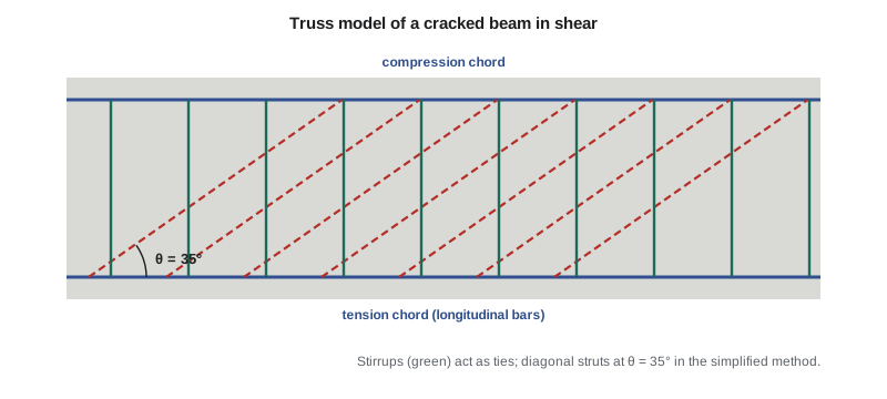
Ritter and Mörsch proposed more than a century ago that a cracked beam with stirrups acts as a truss. The compression zone is the top chord, the longitudinal steel is the bottom chord, the concrete between the inclined cracks forms diagonal struts, and the stirrups are vertical ties. If the struts are inclined at angle \(\theta\) to the axis, a length of beam \(d_v\cot\theta\) is crossed by the crack, and every stirrup in that length carries the force \(A_v f_y\). The shear carried by the stirrups is therefore
where \(A_v\) is the area of all the legs of one stirrup and \(s\) is the stirrup spacing. A flatter strut angle means more stirrups are crossed and more shear is carried, but it also means more tension in the longitudinal steel and more compression in the struts. The truss model also explains why the longitudinal bars need extra force near supports and why the web concrete can crush if the shear is too high.
A23.3 is built directly on this model, refined by the modified compression field theory developed at the University of Toronto. The concrete contribution \(V_c\) represents the shear carried across the cracks by aggregate interlock, and the strut angle and \(V_c\) both depend on how much the member is strained longitudinally.
Shear resistance in the code
The factored shear resistance in A23.3 is the sum of a concrete term and a steel term, capped by a limit that prevents crushing of the web struts:
Here \(d_v\), the effective shear depth, is the larger of \(0.9d\) and \(0.72h\), and \(\sqrt{f'_c}\) is limited to 8 MPa. The factors \(\beta\) and \(\theta\) can be found by two methods:
- The simplified method, for members not subject to significant axial tension, with \(f_y \le 400\) MPa and \(f'_c \le 60\) MPa: \(\theta = 35°\) and \(\beta = 0.18\) when at least minimum stirrups are provided. For members without stirrups, \(\beta = 230/(1000 + d_v)\), which includes a size effect: deeper members without stirrups fail at lower average shear stress.
- The general method: \(\beta\) and \(\theta\) depend on the longitudinal strain at mid-depth, \(\varepsilon_x\), computed from the factored moment, shear and axial load. A lightly strained section has a steeper crack network, better aggregate interlock and a larger \(\beta\).
where the second factor in \(\beta\) is 1.0 when minimum stirrups are present. \(M_f\) is taken at least equal to \(V_f d_v\). Because the general method rewards members with low strain, it often gives a larger \(V_c\) near supports of simply supported beams, where the moment is small.
Where to design for shear and minimum stirrups
Near a support that introduces compression into the beam, a diagonal crack that would cross the support cannot form, so the critical section is taken at \(d_v\) from the face of the support, and stirrups designed for that shear are continued to the support. Concentrated loads closer to the support than \(2d\) are partly carried directly to the support by arching, but A23.3 still requires care; the simplest conservative approach treats them at full value.
Minimum stirrups are required wherever \(V_f\) exceeds the concrete resistance of a member without stirrups, and in all beams deeper than 750 mm. They stop a diagonal crack from opening suddenly once it forms. The minimum area and maximum spacing are
The spacing limit makes sure that every potential diagonal crack is crossed by at least one or two stirrups. Stirrups must also be anchored at both ends, with hooks around longitudinal bars, because a stirrup is useless if it pulls out before reaching yield.
Worked problem
Stirrups for the office floor beam
Design stirrups for the office beam: \(w_f = 43.0\) kN/m, simple span 7.5 m, \(b_w = 350\) mm, \(h = 600\) mm, \(d = 540\) mm, \(f'_c = 30\) MPa, 10M U-stirrups (\(A_v = 200\) mm², \(f_y = 400\) MPa). Use the simplified method.
Show solution
- \[d_v = \max(0.9 \times 540,\ 0.72 \times 600) = 486\ \text{mm}\]
- Shear at \(d_v\) from the support (measured from the centre of the support for this first pass):
- \[V_f = 161 - 43.0(0.486) = 140\ \text{kN}\]
- Without stirrups, \(\beta = 230/(1000 + 486) = 0.155\) and \(V_c = 0.65(0.155)\sqrt{30}(350)(486) = 94\) kN \(< 140\) kN, so stirrups are required. With minimum stirrups, \(\beta = 0.18\):
- \[V_c = 0.65(1.0)(0.18)\sqrt{30}(350)(486) = 109\ \text{kN} \qquad V_s = 140 - 109 = 31\ \text{kN}\]
- \[s = \frac{0.85(200)(400)(486)\cot 35°}{31\,000} = 1520\ \text{mm}\]
- Limits: \(0.125(0.65)(30)(350)(486)/1000 = 415\) kN \(> V_f\), so \(s_{max} = 0.7(486) = 340\) mm. Minimum area: \(s \le 200(400)/(0.06\sqrt{30}(350)) = 696\) mm. Crushing limit: \(0.25(0.65)(30)(350)(486) = 829\) kN \(\gg 140\) kN.
Answer: The spacing limit governs: 10M U-stirrups at 325 mm throughout. The concrete term almost carries the shear by itself; the stirrups are there mainly to give the beam a ductile, truss-like behaviour.
Worked problem
Stirrups for the maintenance bay girder
The maintenance bay girder spans 9.0 m with \(b_w = 400\) mm (web width for shear), \(h = 700\) mm, \(d = 630\) mm, \(f'_c = 35\) MPa. It carries \(w_f = 49.4\) kN/m plus a factored concentrated load of 250 kN from the hoist support, 1.5 m from the left support. Design the stirrups near the left support.
Show solution
- Left reaction: \(R = 49.4(9.0)/2 + 250(7.5/9.0) = 222 + 208 = 431\) kN.
- \[d_v = \max(567,\ 504) = 567\ \text{mm} \qquad V_c = 0.65(0.18)\sqrt{35}(400)(567) = 157\ \text{kN}\]
- At \(d_v\): \(V_f = 431 - 49.4(0.567) = 403\) kN and \(V_s = 246\) kN.
- \[s = \frac{0.85(200)(400)(567)(1.428)}{246\,000} = 224\ \text{mm}\]
- Check the stricter spacing limit: \(0.125(0.65)(35)(400)(567) = 645\) kN \(> 403\) kN, so \(s_{max} = 0.7(567) = 397\) mm. Just left of the load \(V_f = 357\) kN needs \(s = 275\) mm. Beyond the load \(V_f = 106\) kN \(< V_c\), and only minimum stirrups at no more than 397 mm are needed.
Answer: Use 10M U-stirrups at 200 mm from the support to beyond the hoist load, then 375 mm. Stirrup spacing is usually changed in a few steps, not at every section.
Sofia's program evaluates the shear at several sections and reports the spacing at each, so Owen can choose the steps.
import math
# Shear design by the CSA A23.3 simplified method, with a general-method check
phic, phis, fy, Es = 0.65, 0.85, 400.0, 200000.0
Av = 200.0                                   # 10M U-stirrup, two legs
cot = 1 / math.tan(math.radians(35))

def design(name, fc, bw, d, h, wf, P, a, L, xs):
    """Simple span, uniform load wf (kN/m) plus point load P (kN) at a (m) from the left;
    xs = sections (m from the left support) where the stirrup spacing is found."""
    dv = max(0.9 * d, 0.72 * h)
    rt = min(math.sqrt(fc), 8.0)
    Vc = phic * 1.0 * 0.18 * rt * bw * dv / 1000
    Vmax = 0.25 * phic * fc * bw * dv / 1000
    RL = wf * L / 2 + P * (L - a) / L
    s_max = min(0.7 * dv, 600)
    s_min_av = Av * fy / (0.06 * math.sqrt(fc) * bw)
    print(f"{name}: dv = {dv:.0f} mm, Vc = {Vc:.0f} kN, Vr,max = {Vmax:.0f} kN, RL = {RL:.0f} kN")
    for x in [dv / 1000] + xs:
        V = RL - wf * x - (P if x > a else 0)
        V = abs(V)
        Vs = max(V - Vc, 0.0)
        s = phis * Av * fy * dv * cot / (Vs * 1000) if Vs > 0 else float("inf")
        limit = s_max if Vs <= 0.125 * phic * fc * bw * dv / 1000 else min(0.35 * dv, 300)
        s_use = min(s, limit, s_min_av)
        print(f"   x = {x:5.2f} m  Vf = {V:6.0f}  Vs req = {Vs:5.0f} kN  s = {s_use:4.0f} mm")
    return dv

dv = design("office floor beam", 30, 350, 540, 600, 43.0, 0.0, 0.0, 7.5, [1.5, 2.5])
design("maintenance bay girder", 35, 400, 630, 700, 49.4, 250.0, 1.5, 9.0, [1.49, 1.51, 3.0])

# General method at dv for the office beam: strain-based beta and theta
fc, bw, As = 30, 350, 2000.0
x = dv / 1000
Vf = 43 * 7.5 / 2 - 43 * x
Mf = (43 * 7.5 / 2) * x - 43 * x**2 / 2
ex = (Mf * 1e6 / dv + Vf * 1e3) / (2 * Es * As)
beta = 0.40 / (1 + 1500 * ex)                # with at least minimum stirrups
theta = 29 + 7000 * ex
Vc = phic * beta * math.sqrt(fc) * bw * dv / 1000
print(f"general method at dv: Mf = {Mf:.0f} kN.m, eps_x = {ex*1000:.3f}e-3, beta = {beta:.3f}, "
f"theta = {theta:.1f} deg, Vc = {Vc:.0f} kN")office floor beam: dv = 486 mm, Vc = 109 kN, Vr,max = 829 kN, RL = 161 kN x = 0.49 m Vf = 140 Vs req = 31 kN s = 340 mm x = 1.50 m Vf = 97 Vs req = 0 kN s = 340 mm x = 2.50 m Vf = 54 Vs req = 0 kN s = 340 mm maintenance bay girder: dv = 567 mm, Vc = 157 kN, Vr,max = 1290 kN, RL = 431 kN x = 0.57 m Vf = 403 Vs req = 246 kN s = 224 mm x = 1.49 m Vf = 357 Vs req = 200 kN s = 275 mm x = 1.51 m Vf = 106 Vs req = 0 kN s = 397 mm x = 3.00 m Vf = 32 Vs req = 0 kN s = 397 mm general method at dv: Mf = 73 kN.m, eps_x = 0.364e-3, beta = 0.259, theta = 31.5 deg, Vc = 157 kN
The last line of the output shows the general method at work. At \(d_v\) from the support of the office beam the moment is small, the longitudinal strain is only 0.36 × 10⁻³, and \(\beta\) rises to 0.259 with a flatter strut angle of 31.5 degrees. The concrete alone then resists 157 kN, more than the 140 kN applied. Minimum stirrups are still required because \(V_f\) exceeds the resistance of a member without stirrups, but the general method shows the extra reserve the simplified method leaves on the table.
Longitudinal steel and other details
The truss model shows that diagonal compression pushes the bottom chord apart near the supports, so the longitudinal tension at a section is larger than \(M_f/d_v\) alone. A23.3 requires the longitudinal steel on the flexural tension side to resist this extra force, which matters at simple supports where the bars must be developed beyond the inside face of the support. Lesson 7 returns to this when it checks bar anchorage.
- Stirrups must be closed or hooked around longitudinal bars in their corners, and extend as close to the compression and tension faces as cover allows.
- Beams that support other beams near their bottom need hanger reinforcement to lift the load of the supported beam to the top of the supporting beam.
- Torsion, as in spandrel beams that support slabs on one side, requires closed stirrups and additional longitudinal bars; it is covered in a later course.
- In seismic regions, beam ends need closely spaced hoops for confinement and shear in plastic hinges.
Common mistakes
MistakeUsing \(d\) instead of \(d_v\) in A23.3 shear equations.
Instead\(d_v = \max(0.9d,\ 0.72h)\) in every term.
MistakeDesigning the stirrups for the shear at the face of the support.
InsteadThe critical section is at \(d_v\) from the face when the support puts the beam in compression.
MistakeCounting only one leg of a U-stirrup.
Instead\(A_v\) is the area of all legs crossing the crack: two for a U-stirrup.
MistakeOmitting stirrups because the concrete carries the shear.
InsteadProvide minimum stirrups wherever \(V_f\) exceeds the resistance without stirrups, and in beams over 750 mm deep.
Summary and key terms
- Diagonal cracking makes shear failures sudden; design aims for flexure to govern.
- After cracking, a beam with stirrups acts as a truss of concrete struts and steel ties.
- A23.3: \(V_r = \phi_c\lambda\beta\sqrt{f'_c}b_wd_v + \phi_sA_vf_yd_v\cot\theta/s\), with \(\beta = 0.18\), \(\theta = 35°\) in the simplified method.
- The general method computes \(\beta\) and \(\theta\) from the longitudinal strain \(\varepsilon_x\).
- Minimum stirrups and maximum spacing ensure every diagonal crack is crossed and held closed.
- The office beam needs 10M at 325 mm; the maintenance girder needs 10M at 200 mm near the hoist load.
- Diagonal tension crack
- An inclined crack caused by principal tensile stress from combined shear and flexure.
- Stirrup
- Transverse reinforcement enclosing the longitudinal bars that resists shear as a tie.
- Truss model
- An idealization of a cracked beam as compression struts and tension ties.
- Aggregate interlock
- Shear transfer across a crack by the roughness of the crack faces.
- Dowel action
- Shear carried by longitudinal bars bending across a crack.
- Effective shear depth
- dv, the larger of 0.9d and 0.72h.
- Critical section for shear
- The section near a support at which shear design begins.
- Hanger reinforcement
- Stirrups that transfer the reaction of a supported beam to the top of the supporting beam.
Practice problems
Work each problem on paper first, then reveal the answer to check.
Find \(V_c\) by the simplified method for \(b_w = 300\) mm, \(h = 500\) mm, \(d = 440\) mm, 25 MPa, with minimum stirrups.
Show answer
\(d_v = 396\) mm; \(V_c = 0.65(0.18)(5)(300)(396) = 69.5\) kN.
What spacing of 10M U-stirrups gives \(V_s = 150\) kN with \(d_v = 486\) mm?
Show answer
\(s = 0.85(200)(400)(486)(1.428)/150\,000 = 315\) mm.
Why is the critical section moved away from the face of a support?
Show answer
Compression from the support prevents a diagonal crack from crossing it there; the first crack that can form starts about one effective depth away.
What happens to \(\beta\) in the general method as \(\varepsilon_x\) increases?
Show answer
It decreases: wider cracks transfer less shear by aggregate interlock.
Why must stirrups be anchored around longitudinal bars?
Show answer
A stirrup must develop its yield force at the crack; without anchorage it pulls out early.
Lesson quiz · 5 questions
Score 60% or more to complete this lesson.
Create a free account to save your progress, take quizzes and earn a certificate.