
CIV-241 · Lesson 4 of 12 · 23 min
Rock mass characterization
A laboratory specimen of rock is a small cylinder cut from between the fractures. The rock that engineers actually deal with in a slope, a tunnel or a foundation is a rock mass: intact blocks of rock separated by joints, bedding planes, faults, foliation and other discontinuities. The rock mass is almost always weaker, more deformable and more permeable than the intact rock, often by a large factor, because its behaviour is controlled by the discontinuities. Rock mass characterization is the systematic description of those discontinuities and the rock between them, leading to classification systems that engineers use for preliminary design of slopes, tunnels and foundations.
Types of discontinuities
Discontinuity is the general term for any break in the rock with low or no tensile strength. The main types are:
- Joints: fractures with no visible movement parallel to their surfaces. They form from cooling, unloading as overlying rock erodes, folding and regional stresses, and they usually occur in sets of roughly parallel fractures. Two or three sets plus random joints are common, cutting the rock into blocks.
- Bedding planes: surfaces between sedimentary layers, often persistent over large areas and sometimes coated or filled with clay.
- Foliation and cleavage: planes of weakness in metamorphic rocks formed by aligned minerals.
- Faults: fractures along which the rock on either side has moved. Faults may contain crushed rock (breccia) and finely ground clay-like gouge, and the rock next to them is often heavily fractured. Fault zones are weak, may carry or block groundwater, and are a common source of problems in tunnels and cuts.
- Shear zones and sheared clay seams: zones of distributed movement, including bedding-plane shears in shale sequences, whose strength may have fallen to a low residual value.
Describing discontinuities
Each discontinuity set is described by a standard list of properties, because each property affects the strength, deformability or permeability of the rock mass.
- Orientation: the dip and dip direction of the discontinuity plane, measured with a compass-clinometer. Orientation relative to the slope face or tunnel axis is often the single most important factor in stability.
- Spacing: the perpendicular distance between adjacent discontinuities of one set. Closely spaced joints give small blocks and a weaker, more permeable mass.
- Persistence: how far a discontinuity extends. A highly persistent joint can form a complete sliding surface; a short one must break intact rock to fail.
- Roughness and waviness: rough, undulating surfaces must ride up over asperities to slide, which increases shear strength; smooth, planar surfaces offer little resistance beyond the basic friction of the rock.
- Aperture and infilling: the width of the opening and the material in it. Open joints transmit water; joints filled with soft clay can be very weak, especially if the filling is thicker than the roughness amplitude so that rock walls never touch.
- Wall strength and weathering: weathered joint walls are weaker than fresh rock.
- Seepage: whether the discontinuity is dry, damp, wet, dripping or flowing. Water pressure in joints reduces the normal stress and therefore the frictional resistance.
Rock quality designation (RQD)
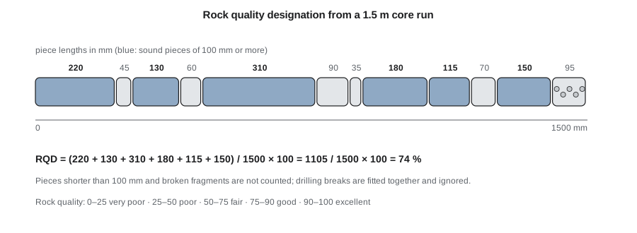
Rock quality designation, introduced by Deere in the 1960s, is a simple index of fracturing measured on drill core. RQD is the sum of the lengths of intact core pieces that are at least 100 mm long, divided by the total length of the core run, expressed as a percentage. Only pieces of sound rock are counted, and breaks caused by drilling or handling should be ignored, so the logger must judge whether each break is natural. RQD should be measured on core of about 50 mm diameter or larger, and logged immediately after drilling, before the core deteriorates.
| RQD (%) | Rock quality |
|---|---|
| 0–25 | Very poor |
| 25–50 | Poor |
| 50–75 | Fair |
| 75–90 | Good |
| 90–100 | Excellent |
RQD is quick and universal, which is why it appears on almost every rock core log. It also has limitations. It ignores joint orientation, condition and infilling; it depends on the direction of the borehole relative to the joint sets, so a vertical hole parallel to vertical joints can give a misleadingly high value; and the 100 mm threshold means that a rock with joints at 90 mm spacing and one at 110 mm spacing can give very different RQD values for nearly the same rock mass. RQD is best used as one input to a fuller classification, not as a stand-alone design parameter.
Worked problem
RQD of a core run
Marcus logs a 1.50 m core run of basalt from the highway cut. The natural pieces, in order, measure (mm): 220, 45, 130, 60, 310, 90, 35, 180, 115, 70, 150, and 95 mm of broken fragments. Calculate the RQD and describe the rock quality.
Show solution
- Count only pieces at least 100 mm long: 220, 130, 310, 180, 115 and 150 mm.
- \[\sum = 220 + 130 + 310 + 180 + 115 + 150 = 1105\ \text{mm}\]
- Divide by the run length:
- \[\text{RQD} = \frac{1105}{1500} \times 100 = 73.7\%\]
- From the table, 50 to 75 per cent is fair.
Answer: RQD is about 74 per cent, fair rock quality, close to the boundary with good.
Estimating RQD without core
Where only exposures are available, such as in a cut face or tunnel wall, RQD can be estimated from the number of joints per cubic metre, called the volumetric joint count \(J_v\). A widely used approximation is \(\text{RQD} \approx 115 - 3.3 J_v\), limited to between 0 and 100 per cent. Another approach uses the average joint spacing along a scanline: with joints spaced randomly at an average frequency \(\lambda\) per metre, the expected RQD is \(100 e^{-0.1\lambda}(0.1\lambda + 1)\). These relations give quick estimates for preliminary assessment, but they are approximate.
# RQD from core pieces and from joint counts
import math

run_length = 1500  # mm
pieces = [220, 45, 130, 60, 310, 90, 35, 180, 115, 70, 150]
long_pieces = [p for p in pieces if p >= 100]
rqd = 100 * sum(long_pieces) / run_length
classes = [(25, "very poor"), (50, "poor"), (75, "fair"), (90, "good"), (101, "excellent")]
quality = next(name for limit, name in classes if rqd < limit)
print(f"RQD from core: {rqd:.1f}% ({quality})")

# From a volumetric joint count in a cut face
for jv in (5, 10, 20, 30):
    est = max(0, min(100, 115 - 3.3 * jv))
    print(f"Jv = {jv:2d} joints/m3 -> RQD ~ {est:.0f}%")

# From scanline joint frequency (Priest and Hudson form)
for lam in (2, 5, 10, 20):
    est = 100 * math.exp(-0.1 * lam) * (0.1 * lam + 1)
print(f"{lam:2d} joints per m along scanline -> RQD ~ {est:.0f}%")RQD from core: 73.7% (fair) Jv = 5 joints/m3 -> RQD ~ 98% Jv = 10 joints/m3 -> RQD ~ 82% Jv = 20 joints/m3 -> RQD ~ 49% Jv = 30 joints/m3 -> RQD ~ 16% 2 joints per m along scanline -> RQD ~ 98% 5 joints per m along scanline -> RQD ~ 91% 10 joints per m along scanline -> RQD ~ 74% 20 joints per m along scanline -> RQD ~ 41%
The Rock Mass Rating (RMR) system
Bieniawski's Rock Mass Rating, developed in the 1970s and revised in 1989, combines several properties into a single number from 0 to 100. Each of five parameters receives a rating, the ratings are summed, and an adjustment is made for discontinuity orientation relative to the structure. The parameters and the approximate range of their ratings in the 1989 version are:
| Parameter | Rating range | What it measures |
|---|---|---|
| 1. Intact rock strength | 0–15 | UCS or point load index |
| 2. RQD | 3–20 | Degree of fracturing in core |
| 3. Discontinuity spacing | 5–20 | Block size |
| 4. Discontinuity condition | 0–30 | Persistence, aperture, roughness, infilling and weathering |
| 5. Groundwater | 0–15 | Inflow or joint water pressure |
| Orientation adjustment | 0 to −60 (depends on application) | Favourable or unfavourable joint orientation for the structure |
| RMR | Class | Description |
|---|---|---|
| 81–100 | I | Very good rock |
| 61–80 | II | Good rock |
| 41–60 | III | Fair rock |
| 21–40 | IV | Poor rock |
| Below 21 | V | Very poor rock |
The RMR value has been correlated with many design quantities: the stand-up time of an unsupported tunnel span, tunnel support recommendations, approximate rock mass cohesion and friction angle, and the rock mass deformation modulus. One widely quoted relation for the deformation modulus in gigapascals is \(E_m = 10^{(RMR - 10)/40}\), which gives about 10 GPa for RMR 50 and about 32 GPa for RMR 70. Correlations like this are approximate and are most useful in feasibility studies and for comparing sites.
Other systems are also widely used. The Q system of Barton and colleagues, developed in Norway, combines RQD, the number of joint sets, joint roughness and alteration, water and stress conditions into a single value on a logarithmic scale, and is common in tunnelling. The Geological Strength Index (GSI), associated with Hoek, is estimated from charts of rock structure and surface condition and feeds directly into the Hoek–Brown strength criterion used in numerical analysis. Experienced practitioners often calculate more than one index and check that they tell a consistent story.
Worked problem
A simple RMR estimate
For the basalt in the highway cut, Ingrid assigns these 1989 ratings from the published tables: intact strength (UCS about 120 MPa) 12; RQD 74 per cent, 13; joint spacing 0.3 to 0.6 m, 10; joint condition, slightly rough with less than 1 mm separation and slightly weathered walls, 25; groundwater, damp, 10. For a slope, one joint set dips steeply out of the face, and she applies an orientation adjustment of −25. Calculate the basic and adjusted RMR and estimate the rock mass modulus.
Show solution
- Basic RMR is the sum of the five ratings:
- \[\text{RMR}_{basic} = 12 + 13 + 10 + 25 + 10 = 70\]
- Adjusted for unfavourable orientation:
- \[\text{RMR} = 70 - 25 = 45\]
- Estimate the deformation modulus from the basic value (the modulus correlation uses the unadjusted rating):
- \[E_m = 10^{(70 - 10)/40} = 10^{1.5} \approx 32\ \text{GPa}\]
Answer: The rock mass is good (class II) in its basic rating, but the unfavourable joint orientation brings the slope rating down to fair (class III, 45). The rock mass modulus is roughly 30 GPa, far below the intact modulus of fresh basalt.
The example shows why orientation matters so much in rock slopes. The same rock mass that would stand steeply if the joints dipped into the slope may need a flatter angle, bolting or a catchment ditch if the joints dip out of it.
Kinematic analysis of rock slopes
Before calculating a factor of safety, an engineer checks whether failure is kinematically possible: whether the geometry of the discontinuities and the slope face lets blocks move. Three classic mechanisms are checked. Plane failure needs a discontinuity that strikes roughly parallel to the face, dips out of it less steeply than the face so it daylights, and dips more steeply than its friction angle. Wedge failure occurs when two discontinuities intersect along a line that plunges out of the face more steeply than the friction angle. Toppling occurs when steep discontinuities dip into the slope and divide the rock into slabs or columns that rotate outward. These checks are done graphically on stereonets, which plot the orientations of planes as points or great circles, or with software.
Provincial highway rock cuts in British Columbia are designed and maintained with these principles, and the province manages rockfall hazard along its mountain highways through rock scaling, bolting, mesh, catchment ditches and fences. Rockfall is one of the most frequent geohazards affecting the highway network.
Common mistakes
MistakeUsing intact rock strength as the strength of the rock mass.
InsteadThe rock mass is weaker and more deformable because of its discontinuities; use rock mass classification and discontinuity strength.
MistakeCounting drilling breaks when calculating RQD.
InsteadCount only natural breaks; mechanical breaks from drilling and handling should be fitted together and ignored.
MistakeReporting RQD without the borehole orientation.
InsteadRQD depends on hole direction relative to the joint sets; record orientation and consider inclined holes.
MistakeIgnoring joint orientation in a slope assessment.
InsteadCheck kinematic feasibility of plane, wedge and toppling failure; orientation often governs stability.
Summary and key terms
- Rock masses are intact blocks separated by discontinuities, and they are weaker, softer and more permeable than intact rock.
- Discontinuities include joints, bedding, foliation, faults and shear zones.
- Each discontinuity set is described by orientation, spacing, persistence, roughness, aperture, infilling, wall strength and seepage.
- RQD is the percentage of a core run made of sound pieces at least 100 mm long; it is quick but ignores joint condition and orientation.
- RMR sums ratings for intact strength, RQD, spacing, joint condition and groundwater, then adjusts for orientation; Q and GSI are alternatives.
- Kinematic analysis checks whether plane, wedge or toppling failure is geometrically possible before stability is calculated.
- Rock mass
- Intact rock together with the discontinuities that cut it, at the scale of an engineering structure.
- Discontinuity
- Any break in rock with little or no tensile strength, such as a joint, bedding plane or fault.
- Joint set
- A group of roughly parallel joints.
- Persistence
- The areal extent or length of a discontinuity.
- RQD
- Rock quality designation: the percentage of a core run made of sound pieces at least 100 mm long.
- RMR
- Rock Mass Rating: a classification summing ratings for strength, RQD, spacing, joint condition and groundwater.
- Gouge
- Fine, clay-like crushed rock in a fault zone.
- Kinematic analysis
- A geometric check of whether blocks can slide or topple given discontinuity and slope orientations.
Practice problems
Work each problem on paper first, then reveal the answer to check.
A 3.0 m core run contains sound pieces totalling 2.1 m that are each at least 100 mm long. What is the RQD?
Show answer
\(2.1/3.0 \times 100 = 70\) per cent, fair.
Why can a vertical borehole give a misleadingly high RQD?
Show answer
If the main joint sets are vertical, the hole runs parallel to them and intersects few joints.
Estimate RQD for a volumetric joint count of 15 joints per cubic metre.
Show answer
\(115 - 3.3 \times 15 = 65.5\), about 65 per cent.
List the five parameters of the RMR system.
Show answer
Intact rock strength, RQD, discontinuity spacing, discontinuity condition and groundwater.
What three conditions are needed for plane failure?
Show answer
The plane strikes roughly parallel to the face, daylights in the face, and dips more steeply than its friction angle.
Using \(E_m = 10^{(RMR - 10)/40}\), estimate the rock mass modulus for RMR 50.
Show answer
\(10^{1.0} = 10\) GPa.
Lesson quiz · 5 questions
Score 60% or more to complete this lesson.
Create a free account to save your progress, take quizzes and earn a certificate.