
CIV-241 · Lesson 12 of 12 · 22 min
Site investigation: boreholes, SPT, CPT, logs and reports
Everything in this course comes together in the site investigation. Its purpose is to build a ground model good enough for the design and construction decisions that depend on it: what lies beneath the site, how the materials will behave, where the groundwater is, and which hazards must be addressed. A good investigation is planned around the geology and the project, not around a fixed number of boreholes per hectare. It is staged, so that early findings guide later work, and it is reported clearly, with honest statements about what is known and what is not. This final lesson follows Kestrel's investigation for the hospital expansion from planning to report.
Planning an investigation
Planning starts with the desk study and site reconnaissance described in lesson 1. Together they produce a preliminary ground model and a list of questions the investigation must answer. For the hospital, the questions were: How deep are the soft glacial lake silts, and how variable? What is the seismic site class? Is any layer liquefiable? Where is the groundwater, and does it vary seasonally? At what depth is a suitable bearing stratum for shallow or deep foundations? Is there any sign of old landslides, buried channels or fill from earlier development?
The scope then follows from the questions, the structure and the geology. Codes and guidelines give typical spacings and depths, but these are starting points. Boreholes are commonly placed at the corners and centre of a building footprint, along the alignment of roads and pipelines at regular intervals, and at locations chosen to test specific features of the model. Depths must extend below the zone significantly stressed by the foundations, often taken as one to two times the footing width for shallow foundations or several pile diameters below the expected pile toe level, and through any soft or liquefiable layers. Where rock is expected, borings should prove it by coring a few metres, to avoid mistaking a boulder in till for bedrock.
In Canada, the National Building Code requires subsurface investigation by a qualified person for the design of foundations, and the Canadian Foundation Engineering Manual published by the Canadian Geotechnical Society gives widely used guidance on investigation planning, sampling and testing. Provincial highway agencies have their own guidelines for road and bridge projects.
Methods of exploration
Several methods are combined on most projects.
- Test pits and trenches, dug with an excavator, allow direct inspection of shallow soils, layering, fill and groundwater seepage, and the collection of large samples. They are cheap and informative to depths of about 3 to 5 m but must be backfilled and compacted carefully, and workers must not enter unsupported deep pits.
- Boreholes are drilled with several methods. Hollow-stem augers advance a continuous auger with a hollow centre through which samples can be taken, and are common in soils above and below the water table. Mud rotary drilling uses drilling fluid to support the hole and is efficient in deep soil profiles. Sonic drilling vibrates a core barrel into the ground and recovers continuous, though somewhat disturbed, cores even in gravel and till with boulders. Rock is cored with diamond-bit core barrels, recovering cylindrical core for logging and testing.
- In situ tests measure properties in place, avoiding sample disturbance. The two most common are the standard penetration test and the cone penetration test, described below. Others include the vane shear test for undrained strength of soft clay, the pressuremeter and dilatometer tests for stiffness, and packer and slug tests for hydraulic conductivity.
- Geophysics images large volumes of ground cheaply between boreholes: seismic refraction and surface wave methods for rock depth and stiffness, electrical resistivity for clay, water and voids, and ground-penetrating radar for shallow features. Geophysical results are interpretations and must be calibrated against boreholes.
- Instrumentation, such as standpipe and vibrating-wire piezometers and inclinometers, is installed in completed boreholes to monitor groundwater and movement over time.
Sampling
Samples are classed by disturbance. Disturbed samples, from auger cuttings or split-spoon samplers, preserve grain size and composition and are suitable for classification and index tests. Undisturbed samples, taken with thin-walled Shelby tubes pushed into soft to firm clays, or with piston samplers and block sampling for sensitive soils, preserve the structure well enough for strength and consolidation testing. No sample is truly undisturbed; sensitive clays in particular lose strength through stress relief and handling, so careful sampling, sealing, transport and storage matter as much as the sampler type.
The standard penetration test (SPT)
The SPT is the most widely used in situ test in North America. A split-spoon sampler of standard dimensions (50 mm outside diameter) at the bottom of a borehole is driven into the soil by a 63.5 kg (140 lb) hammer falling 760 mm (30 in). The sampler is driven 450 mm in three 150 mm increments, and the number of blows for the second and third increments together is the N-value, in blows per 300 mm (or per foot). The test also recovers a disturbed sample for classification.
The N-value correlates with the density of sands and, more loosely, with the consistency of clays, and is used in many empirical design methods for bearing capacity, settlement and liquefaction. It is affected by several factors, the most important being the energy actually delivered to the rods, which varies with hammer type and operation. Results are normalized to an energy ratio of 60 per cent, the average of historical practice, giving \(N_{60}\), and for sands they are further corrected to a reference overburden stress of about 100 kPa to give \((N_1)_{60}\).
| (N₁)₆₀ in sand | Relative density description |
|---|---|
| 0–3 | Very loose |
| 3–8 | Loose |
| 8–25 | Medium dense (compact) |
| 25–42 | Dense |
| Over 42 | Very dense |
Worked problem
Correcting SPT blow counts
In borehole BH-3 at the hospital site, an SPT at 6.0 m depth in sand gives a field N of 14. The automatic hammer on the drill rig has a measured energy ratio of 80 per cent. The water table is at 2.0 m, and the soil unit weight is 19 kN/m³ above and 20 kN/m³ below the water table. Find \(N_{60}\) and \((N_1)_{60}\).
Show solution
- Energy correction:
- \[N_{60} = 14 \times \frac{80}{60} = 18.7\]
- Vertical effective stress at 6.0 m:
- \[\sigma'_v = 19(2.0) + (20 - 9.81)(4.0) = 38.0 + 40.8 = 78.8\ \text{kPa}\]
- Overburden correction with \(p_a = 100\) kPa:
- \[C_N = (100/78.8)^{0.5} = 1.13 \qquad (N_1)_{60} = 1.13 \times 18.7 = 21.1\]
Answer: \(N_{60} \approx 19\) and \((N_1)_{60} \approx 21\): a medium dense (compact) sand. Without the energy correction, the field N of 14 would understate the density, because this hammer delivers more energy than the 60 per cent reference.
The cone penetration test (CPT)
In the CPT, a cone with a 60° apex and a standard base area of 10 cm² on the end of a string of rods is pushed into the ground at a steady 20 mm/s, while sensors record the cone tip resistance \(q_c\), the sleeve friction \(f_s\) along a friction sleeve behind the cone, and, in the piezocone (CPTu), the pore water pressure \(u_2\) just behind the tip. Readings are taken every one or two centimetres, so the CPT gives a nearly continuous profile that reveals thin layers missed by sampling at intervals. A seismic cone adds geophones to measure shear wave velocity.
The CPT does not recover samples, so it is combined with boreholes. Soil type is inferred from charts of tip resistance against friction ratio (\(f_s/q_c\)) or from a soil behaviour type index. Sands give high tip resistance and low friction ratio; clays give low tip resistance, higher friction ratio and, below the water table, high excess pore pressure. Correlations give strength, density, stiffness and liquefaction resistance. The CPT is fast, repeatable and economical in soft to medium dense soils but cannot penetrate dense gravel, cobbles or rock.
Borehole logs
The borehole log is the primary record of an investigation and often the only part of it that survives into construction and future projects. A good log records the location, ground elevation, date, drilling method and personnel; a description of each stratum with depth boundaries; sample types, depths and recovery; in situ test results such as SPT N-values; groundwater observations with the date and time; and any unusual conditions, such as drilling fluid loss, obstructions or gas. Rock core logs add core recovery, RQD, weathering grade, strength, discontinuity descriptions and fracture frequency.
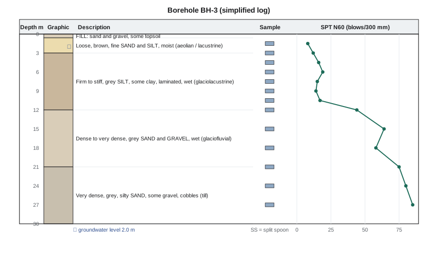
Soil descriptions follow a standard order so that they are consistent between loggers: density or consistency, colour, the principal soil type with secondary components, structure such as layering or fissures, moisture condition, and the geological origin where it can be interpreted. For example: 'Compact, grey, fine to medium SAND, some silt, trace gravel, laminated, wet (glaciofluvial)'. Laboratory classification tests later confirm or correct the field description. The geological origin is especially valuable because it links the log to the ground model.
# SPT corrections and a simple text log for a borehole
import math

ER = 80.0          # hammer energy ratio, per cent
gw_depth = 2.0     # m
g_above, g_below, gw = 19.0, 20.0, 9.81

def sigma_v_eff(z):
    if z <= gw_depth:
        return g_above * z
    return g_above * gw_depth + (g_below - gw) * (z - gw_depth)

def density(n160):
    for lim, d in [(3, "very loose"), (8, "loose"), (25, "compact"), (42, "dense")]:
        if n160 < lim:
            return d
    return "very dense"

spt = [(1.5, 6), (3.0, 9), (4.5, 12), (6.0, 14), (7.5, 11), (12.0, 33), (15.0, 48)]
print(" depth  N   N60  sv'(kPa) (N1)60  description")
for z, n in spt:
    n60 = n * ER / 60
    sv = sigma_v_eff(z)
    cn = min(1.7, (100 / sv) ** 0.5)
    n160 = cn * n60
print(f"{z:5.1f} {n:3d} {n60:5.1f} {sv:8.1f} {n160:6.1f} {density(n160)}")depth N N60 sv'(kPa) (N1)60 description 1.5 6 8.0 28.5 13.6 compact 3.0 9 12.0 48.2 17.3 compact 4.5 12 16.0 63.5 20.1 compact 6.0 14 18.7 78.8 21.0 compact 7.5 11 14.7 94.0 15.1 compact 12.0 33 44.0 139.9 37.2 dense 15.0 48 64.0 170.5 49.0 very dense
Laboratory testing
Laboratory tests characterize the samples. Index tests, such as water content, grain size distribution, Atterberg limits, organic content and unit weight, classify soils and are run on many samples. Engineering tests, such as consolidation (oedometer) tests, triaxial and direct shear strength tests, permeability tests, compaction tests and chemical tests for sulphate and corrosivity, are run on selected undisturbed or representative samples to give design parameters. Rock tests include unconfined compressive strength, point load index, slake durability and discontinuity shear strength. The testing program should be targeted at the questions from the planning stage, not run by habit.
The geotechnical report
The investigation is reported in two parts, sometimes in separate documents. The factual part presents the data: site description, methods, borehole and test pit logs, in situ and laboratory results, groundwater observations and a site plan with test locations. The interpretive part presents the ground model, usually with cross-sections; discusses geological hazards; gives design parameters with their basis; makes recommendations for foundations, excavations, slopes, groundwater control, earthworks and seismic design; and states the limitations of the investigation.
Honesty about uncertainty is a professional obligation and a practical necessity. Ground conditions between boreholes are inferred, not observed, and reports should say so plainly, explain where the model is least certain, and recommend observation and verification during construction. On many contracts, a geotechnical baseline report goes further by defining the ground conditions that bidders should assume, so that the risk of conditions differing from the baseline is allocated clearly between owner and contractor.
For the hospital, Kestrel's report described about 3 m of loose sand and silt over glacial lake silt to about 12 m, dense sand and gravel to about 21 m, and very dense till below; gave site class D for seismic design; concluded that the deeper granular soils were not liquefiable; and recommended driven steel piles bearing in the dense gravel and till, with a construction monitoring program and pile load tests to confirm capacity.
Observation during construction
The ground model is tested most thoroughly when the ground is excavated. Engineering geologists and geotechnical engineers observe foundation excavations, pile driving records, cut slopes and tunnel faces, compare them with the model, and adjust the design where the ground differs. This observational approach, associated with Karl Terzaghi and Ralph Peck, is especially valuable where uncertainty is high: the design is based on the most probable conditions, with planned modifications ready if monitoring shows less favourable conditions. Many expensive failures and disputes trace back to investigations that were never checked against what construction revealed.
Common mistakes
MistakePlanning boreholes on a regular grid without thinking about the geology.
InsteadPlace boreholes to test the ground model, including suspected channels, slides and contacts.
MistakeStopping a boring on the first hard material.
InsteadCore several metres to prove bedrock; boulders in till can be mistaken for rock.
MistakeUsing raw SPT N-values in correlations.
InsteadCorrect for hammer energy and, for sands, overburden stress; measure the hammer energy where possible.
MistakeReporting the ground between boreholes as if it were observed.
InsteadState that conditions between test locations are inferred and recommend verification during construction.
Summary and key terms
- A site investigation builds a ground model to answer specific design questions; it is planned from the desk study and staged.
- Exploration combines test pits, boreholes, in situ tests, geophysics and instruments.
- Disturbed samples serve classification; undisturbed samples serve strength and consolidation testing.
- The SPT gives N-values corrected to \(N_{60}\) and \((N_1)_{60}\); the CPT gives continuous \(q_c\), \(f_s\) and pore pressure profiles.
- Borehole logs record strata, samples, tests and groundwater in a standard format, ideally with geological origin.
- Reports separate factual data from interpretation, state uncertainty, and are verified by observation during construction.
- Site investigation
- The process of exploring and testing the ground to build a ground model for design and construction.
- Standard penetration test
- An in situ test counting blows of a standard hammer to drive a split-spoon sampler 300 mm.
- N60
- An SPT blow count normalized to a 60 per cent hammer energy ratio.
- Cone penetration test
- An in situ test pushing an instrumented cone into the ground at a constant rate.
- Shelby tube
- A thin-walled tube pushed into soft soil to obtain a relatively undisturbed sample.
- Borehole log
- The record of strata, samples, tests and groundwater observed in a borehole.
- Geotechnical baseline report
- A contract document defining the ground conditions to be assumed for bidding and risk allocation.
- Observational method
- An approach that designs for probable conditions and adjusts using monitoring during construction.
Practice problems
Work each problem on paper first, then reveal the answer to check.
A field SPT N of 20 is obtained with a hammer of energy ratio 45 per cent. What is \(N_{60}\)?
Show answer
\(20 \times 45/60 = 15\).
Why should a boring that hits hard material in till be cored for several metres?
Show answer
To confirm it is bedrock and not a boulder.
What three measurements does a piezocone record?
Show answer
Tip resistance \(q_c\), sleeve friction \(f_s\) and pore water pressure \(u_2\).
What is the difference between the factual and interpretive parts of a geotechnical report?
Show answer
The factual part presents data; the interpretive part presents the ground model, parameters, hazards and recommendations.
Give the standard order of a soil description.
Show answer
Density or consistency, colour, principal soil type with secondary components, structure, moisture and geological origin.
What is the advantage of the CPT over the SPT?
Show answer
It gives a nearly continuous, repeatable profile that reveals thin layers, though it recovers no sample.
Lesson quiz · 5 questions
Score 60% or more to complete this lesson.
Create a free account to save your progress, take quizzes and earn a certificate.