
BLR-310 · Lesson 12 of 12 · 18 min
Capstone: laying out a transition and a nozzle set for a vessel
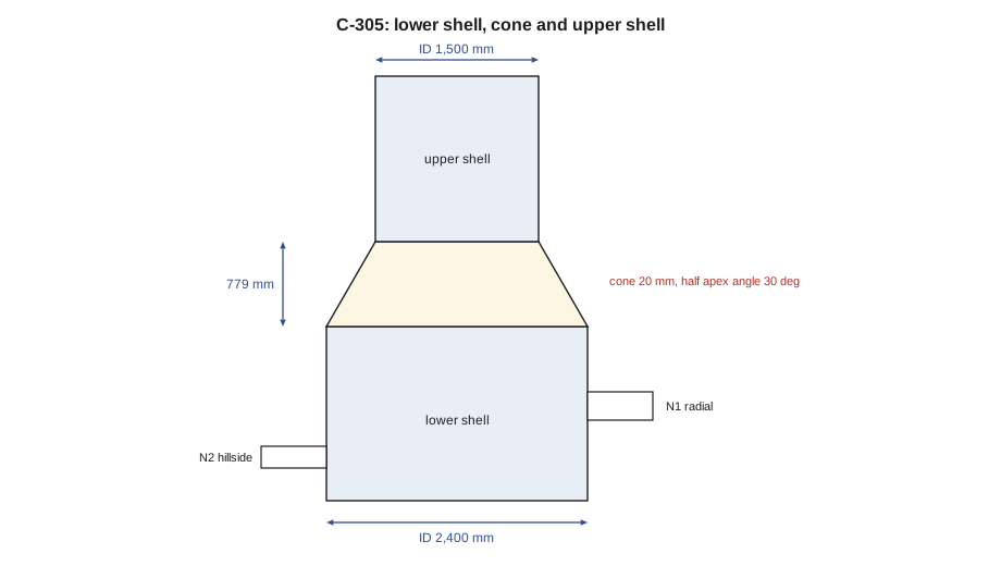
The last job of the winter is the one Joanne has been saving. Northgate is adding a stripper column, C-305, and Ironbridge has the order for its middle section: a lower shell course of 2,400 mm (96 in) inside diameter, a concentric cone up to an upper shell course of 1,500 mm (60 in) inside diameter, and two nozzles on the lower course. The shell plate is 20 mm (3/4 in), and so is the cone. The section is built to ASME Section VIII, Division 1, with Northgate's specification on top. Joanne gives Kiera the drawing and the job file and tells her she is the lead hand on the layout and fit-up, with Joanne and Harjit checking. "Everything you've done this winter is on this one drawing," Joanne says. "A cone, two nozzles on a curved shell, a CNC file, a head-type fit at both ends of the cone. Take it from the drawing to a fitted section, and show me every number." This capstone follows Kiera through the review, the development, the file, the cutting, the forming, the fit-up and the record.
Reading the drawing
Kiera starts by reading the drawing and listing what it fixes. The cone's half apex angle is 30 degrees, with no knuckle at either end. Section VIII allows a cone-to-cylinder junction without a knuckle up to a half apex angle of 30 degrees, provided the junction is checked by the designer for the reinforcement it needs; the design engineer has done that, and the drawing shows the junction welds as full penetration with no extra reinforcing ring. The lower course carries two nozzles: N1, an NPS 8 radial nozzle at 90 degrees, and N2, an NPS 4 hillside nozzle at 180 degrees, offset 600 mm (24 in) from its radial line to line up with a reflux line. The cone's two seams are to be at 45 and 225 degrees, staggered from the shells' long seams at 0 and 180 degrees. Everything is dimensioned to the inside.
| Item | Drawing information | What it decides |
|---|---|---|
| Cone | 30 degree half apex angle, no knuckle, 20 mm (3/4 in) | Pattern radii and sector angle; two pieces |
| Cone seams | At 45 and 225 degrees | Stagger from shell seams at 0 and 180 |
| N1 | NPS 8 radial, 90 degrees | Opening and neck cut on course 1 |
| N2 | NPS 4 hillside, 180 degrees, offset 600 mm (24 in) | Lopsided opening and neck |
| Dimensions | All to the inside | Develop on the mean line |
Developing the cone
The cone's pattern comes from lessons 3 and 4. Kiera works on the mean line: the mean radius of the lower end is the inside radius plus half the thickness, and the same for the upper end. With a 30 degree half apex angle, the pattern radii are the mean radii divided by the sine of 30 degrees, which is a half, so each pattern radius is twice its mean radius. The sector angle is 360 degrees times the sine of the half apex angle, exactly 180 degrees. The cone's pattern is half a ring. The cone's height between the two ends, from the difference in mean radii divided by the tangent of 30 degrees, is the dimension she will check when it is fitted.
Half a ring with an outer radius over 2.4 m (96 in) is far too big for one plate, so she splits it along elements into two pieces of 90 degrees, one for each seam position. The code works out the pieces, checks them against the shop's plate size, and gives the nozzle marks for the lower course.
# C-305 capstone: cone pattern, plate check and nozzle marks (metric)
import math
from math import gcd
MODE = "mm"

def frac(x, den=16):
    sign = "-" if x < 0 else ""
    n = round(abs(x) * den); whole, rem = divmod(n, den)
    if rem == 0:
        return f"{sign}{whole} in"
    g = gcd(rem, den)
    return f"{sign}{whole} {rem // g}/{den // g} in" if whole else f"{sign}{rem // g}/{den // g} in"

def show(x):
    x = 0.0 if abs(x) < 1e-6 else x
    return f"{x:,.0f} mm" if MODE == "mm" else frac(x)
Db, Ds, t = 2400, 1500, 20        # inside diameters of the lower and upper shells, cone plate thickness
half = math.radians(30)         # half apex angle of the cone
Rb, Rs = (Db + t) / 2, (Ds + t) / 2   # mean radii (thickness measured square to the surface, simplified)
h = (Rb - Rs) / math.tan(half)
Lb, Ls = Rb / math.sin(half), Rs / math.sin(half)
ang = 360 * math.sin(half)
print("cone height", show(h), " pattern radii", show(Lb), "/", show(Ls), f" sector {ang:.1f} deg")
pieces = 2
a = math.radians(ang / pieces)                 # angle of each piece
# lay each piece symmetric about a vertical line, chord along the plate's length
pts = [(R * math.sin(f), R * math.cos(f)) for R in (Lb, Ls) for f in [a * (k / 40 - 0.5) for k in range(41)]]
xs, ys = [p[0] for p in pts], [p[1] for p in pts]
long_, wide = max(xs) - min(xs), max(ys) - min(ys)
print(f"each of {pieces} pieces is {ang / pieces:.0f} deg and needs {show(long_)} by {show(wide)} of plate")
plate = (6000, 2440)
print("plate available", show(plate[0]), "by", show(plate[1]), "->", "one piece per plate fits" if long_ <= plate[0] and wide <= plate[1] else "nest differently")
# nozzle N1 (radial) on the lower shell, outside radius
Ro = Db / 2 + 20
for name, d, e in [("N1 NPS 8 radial, lower shell", 219.1, 0), ("N2 NPS 4 hillside, lower shell", 114.3, 600)]:
    c = Ro * math.asin(e / Ro)
    print(f"{name}: ", end="")
    marks = []
    for k in range(4):
        th = math.pi / 2 * k
        lat = e + d / 2 * math.sin(th)
        marks.append(Ro * math.asin(lat / Ro) - c)
print("around-shell marks at 0/90/180/270:", ", ".join(show(m) for m in marks))cone height 779 mm pattern radii 2,420 mm / 1,520 mm sector 180.0 deg each of 2 pieces is 90 deg and needs 3,422 mm by 1,345 mm of plate plate available 6,000 mm by 2,440 mm -> one piece per plate fits N1 NPS 8 radial, lower shell: around-shell marks at 0/90/180/270: 0 mm, 110 mm, 0 mm, -110 mm N2 NPS 4 hillside, lower shell: around-shell marks at 0/90/180/270: 0 mm, 67 mm, 0 mm, -65 mm
Each cone piece fits on one plate, with its chord along the plate's length. The two pieces would not both fit on one plate even turned end for end, so she orders two plates, and the offcuts go to the nozzle reinforcing pads and clips. The nozzle marks show N1's opening very slightly wider around than its diameter, as lesson 8 described, and N2's lopsided opening, wider on its high side.
The file and the first check
The CNC programmer, Dustin, draws the cone pieces from Kiera's sketch and sends her the nest for checking. Following Joanne's four steps from lesson 11, she measures the pieces in the drafting program. The outer radius is 2,400 mm (96 in) and the inner 1,500 mm (60 in): the inside radii doubled, not the mean radii. The file would cut a cone whose large end was about 63 mm (2 3/8 in) short around its circumference. Dustin had entered the drawing's inside diameters. He corrects the radii to 2,420 mm (96 3/4 in) and 1,520 mm (60 3/4 in), Kiera measures again, checks the kerf setting and runs the simulation, and the first piece is cut. It measures within 1 mm (1/16 in) on both radii and the straight edges. Joanne adds the mistake to her list of why every file gets a hand check.
| Check | First file | Corrected file |
|---|---|---|
| Outer pattern radius | 2,400 mm (96 in) (inside basis) | 2,420 mm (96 3/4 in) (mean basis) |
| Inner pattern radius | 1,500 mm (60 in) | 1,520 mm (60 3/4 in) |
| Sector per piece | 90 degrees | 90 degrees |
| Effect on the large end | About 63 mm (2 3/8 in) short in circumference | Correct |
The nozzle openings
N1 and N2 are laid out on course 1's flat plate before rolling, by the method of lesson 8. Kiera transfers the orientation lines onto the plate: 90 degrees for N1 and 180 degrees for N2, as arc lengths on the outside radius from the plate's 0 degree edge, and the elevation lines from the course's lower edge. At N2, she marks the centre of its opening not on the 180 degree line but at the arc for its offset from that line, then lays out both openings point by point and joins the points with a batten. Neither opening is larger than a quarter of the shell's diameter, so both are cut flat. She writes the nozzle number, size and the words "hillside, high side up" inside N2's outline, so no one mistakes which way the lopsided hole should face.
Their necks are developed by the parallel-line method, with each line's length from the shell surface to the flange face. N2's lines vary by nearly a quarter of its projection from one side to the other. Following Harjit's practice, she cuts both necks 3 mm (1/8 in) long.
Forming
Course 1 is rolled with its two nozzle openings already cut. On the first pass, the roll operator, Gus, watches the plate near N1, where the opening makes the plate weaker, and adds a light extra pass there to stop a flat spot forming. The cone pieces are rolled on the cone-rolling attachment with their element lines kept parallel to the rolls, as lesson 3 described. Each is checked with a template cut to the cone's large-end arc and a straightedge along the elements. The two pieces are fitted to each other on the layout table, their seams tacked, and the cone's large and small ends measured by tape: both within 2 mm (1/16 in) of the mean circumferences.
Fitting the cone
Course 1 stands on the fitting table with its top end up. Kiera checks its roundness at the top: within 5 mm (3/16 in), well inside the out-of-roundness limit. She measures its outside circumference and the cone's large-end outside circumference and works out the even offset per side, 1 mm (1/32 in), within the quarter-thickness limit. The cone is lifted on, turned until its seams are at 45 and 225 degrees, and its large end fitted to course 1's top with the offset spread evenly, as in lesson 10. Then she checks the small end: the height from course 1's top to the cone's small end at eight stations. The readings vary by 3 mm (1/8 in), within the drawing's limit for the upper shell to stand plumb.
Course 2, the upper shell, is fitted to the cone's small end the same way. The final check is plumb: with the section standing, Kiera hangs a plumb line from the top of course 2 at four stations and measures to the bottom of course 1. The upper shell is concentric with the lower within 3 mm (1/8 in), and the overall height from course 1's bottom to course 2's top matches the drawing.
Fitting the nozzles
N1's neck goes into its opening with its flange held level and square to the vessel's axis by a magnetic level and a square from the shell's reference line. Kiera measures its projection: 2 mm (1/16 in) long, so she trims the neck and tacks it. N2 takes longer. Its lopsided neck must sit with its long side down, and its flange face must be parallel to N1's direction but 600 mm (24 in) off the radial line. She sets the flange with a straightedge laid across from the 180 degree reference marks, checks the offset at the flange face with a tape and a square, and finds the neck needs 4 mm (3/16 in) more trimming on its high side to bring the flange level. After trimming, both nozzles' bolt holes straddle their centre lines, the projections match the drawing, and the reinforcing pads are fitted around both necks with their telltale holes at the bottom.
| Point | Required | Measured |
|---|---|---|
| Course 1 roundness at the top | Within the code's limit | 5 mm (3/16 in) difference |
| Cone large-end offset | Up to ¼ t | 1 mm (1/32 in) even, worst 2 mm (1/16 in) |
| Cone small-end level | Drawing limit | 3 mm (1/8 in) variation |
| Upper shell concentricity | Drawing limit | 3 mm (1/8 in) |
| N1 projection | Drawing dimension | Trimmed 2 mm (1/16 in); correct |
| N2 projection and offset | Drawing dimensions | Trimmed 4 mm (3/16 in) on the high side; correct |
The record and the release
Harjit checks every point on Kiera's fit-up sheets, measures the nozzle projections and offsets himself, and signs the hold points for the two cone seams, the two cone-to-shell seams and the two nozzles. The record includes the hand calculations for the cone and the nozzle openings, the corrected CNC file with Kiera's check sheet, the heat number transfer for every part, and the readings at each step. Welding starts the next morning.
At the end of the week, Joanne sits down with Kiera to go over the winter. Kiera has developed parallel-line patterns, cones, eccentric cones and transitions; found the lines where cylinders meet cylinders and cones; laid out nozzle openings on flat plate; checked, marked and fitted heads; and turned patterns into CNC files and caught the mistakes in them. The common thread, Joanne says, is the one she started the winter with: every pattern is a set of true lengths on the right line of the plate, and every pattern is checked before it is cut. In Pressure Equipment Codes, the next course, Kiera goes into the rules behind the drawings she has been building to: how the codes set thicknesses, joint categories, inspection and the stamps on the nameplate.
Common mistakes
MistakeAccepting a CNC file because it looks right on screen.
InsteadMeasure the key dimensions against a hand calculation; C-305's first file was on the inside basis.
MistakeMarking a hillside opening on the radial line.
InsteadMark its centre at the arc for its offset, and label which side is high.
MistakeFitting the cone with its seams wherever they fall.
InsteadTurn the cone to put its seams at the drawing's positions, staggered from the shell seams.
MistakeChecking only the cone's large end.
InsteadCheck the small end's level, then the upper shell's plumb and concentricity.
MistakeTacking nozzles at their calculated length.
InsteadCut long, fit, measure and trim before tacking.
Summary and key terms
- A 30 degree half apex cone has pattern radii twice its mean radii and a 180 degree sector.
- Large cones are split along elements into pieces that fit the plate, with seams at the drawing's positions.
- Every CNC file is checked by hand calculation, kerf setting, simulation and first-part measurement.
- Nozzle openings on flat plate are laid out point by point; hillside openings are lopsided and labelled.
- The cone is fitted with the offset spread, its seams placed, and its small end checked at eight stations.
- The fit-up record holds the calculations, the file check, the heat numbers and every reading.
- Stripper column
- A process vessel in which a vapour removes lighter components from a liquid.
- Cone-to-cylinder junction
- The joint between a cone and a shell, where the change of shape concentrates stress.
- Concentric
- Sharing the same centre line.
- Lead hand
- The tradesperson in charge of a task on the shop floor.
- Hold point
- A step in the inspection and test plan that must be signed before work goes on.
Practice problems
Work each problem on paper first, then reveal the answer to check.
What is the sector angle of a cone with a half apex angle of 30 degrees?
Show answer
360 × sin 30° = 180 degrees.
If a cone's mean radius at its large end is 1,220 mm (48 3/8 in) and its half apex angle is 30 degrees, what is its outer pattern radius?
Show answer
Mean radius ÷ sin 30° = 2,440 mm.
Why did Dustin's first file make the cone too small?
Show answer
He developed it on the inside diameters instead of the mean diameters.
Why does Kiera write "hillside, high side up" inside N2's outline?
Show answer
So no one cuts or fits the lopsided opening the wrong way round.
Lesson quiz · 5 questions
Score 60% or more to complete this lesson.
Create a free account to save your progress, take quizzes and earn a certificate.