
BLR-310 · Lesson 1 of 12 · 21 min
Pattern development in boilermaker work
In November, after Tank 15 is handed over, Kiera goes back into Ironbridge's fabrication shop for the winter. Her first morning, Joanne Pellerin hands her a roll of drawings and a cardboard tube full of old sheet metal templates, some of them stamped with job numbers from twenty years ago. "Last winter you learned to lay out flat plate and straight cylinders," Joanne says. "This winter it's the shapes that don't lie flat on the drawing: cones, transitions, elbows, tees, nozzles cut into curved shells. Every one of them has to be cut from a flat plate and then bent into a shape that matches a drawing. Getting from the drawing to the flat shape is called pattern development, and it's the oldest skill in the trade." This lesson introduces the ideas behind every pattern in the course: what a development is, which surfaces can be developed, the three methods for developing them, true lengths, and the thickness allowance that decides which line of the plate the pattern describes.
What a pattern is
A pattern, or development, is the flat shape that, when it is rolled, bent or formed, becomes the part on the drawing. A cylinder's pattern is a rectangle whose length is the circumference. A cone's pattern is a sector of a circle. A square-to-round transition's pattern is a fan of triangles and flat faces. Boilermakers, sheet metal workers and pipefitters all develop patterns, and the methods are the same in each trade; what changes is the thickness of the material and the allowances that come with it.
In a boilermaker shop, patterns end up in three forms. Small parts are laid out directly on the plate with a soapstone, a scriber, a steel rule, a trammel and a set of dividers. Repeated parts are laid out once on thin sheet metal or heavy cardboard as a template, then traced onto each plate. Large or complex parts are drawn on a computer and sent to the CNC cutting table as a file of points. Kiera will learn all three, but Joanne insists that she learn the hand method first. "When the CNC file is wrong, and one day it will be, the person who can lay it out by hand is the one who catches it."
Surfaces that can and cannot be developed
Not every shape can be cut from flat plate and bent without stretching. A surface that can be unrolled flat without stretching or tearing is called developable. Cylinders, cones and the flat faces of prisms and pyramids are developable, because each is made of straight lines that lie in the surface, and the surface can be rolled along those lines like a sheet of paper. A transition built from flat triangles and parts of cones is developable for the same reason.
Spheres, ellipsoidal heads, torispherical heads and the knuckles of flanged heads are not developable. They curve in two directions at once, so a flat plate must stretch or shrink to take their shape. Those parts are pressed, spun or formed in segments by specialist head manufacturers, and the boilermaker buys them finished. Lesson 9 covers how heads are ordered, checked and fitted, and how a shop estimates the size of the flat blank that a head maker starts from, but the head itself is not laid out by pattern development in the way a cone is.
| Surface | Developable? | How it is made in the shop |
|---|---|---|
| Cylinder (shell course, duct, pipe) | Yes | Rectangle rolled to a circle |
| Right cone and truncated cone | Yes | Sector or part sector rolled on the rolls or brake-formed |
| Eccentric cone | Yes, by triangulation | Pattern built from triangles, then formed |
| Square-to-round transition | Yes, by triangulation | Flat triangles and cone parts, brake-formed |
| Sphere, ellipsoidal or torispherical head | No | Bought from a head maker, pressed or spun |
| Knuckle on a flanged cone | No | Formed by the head maker or in segments |
Three methods of development
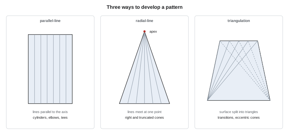
Every developable surface can be laid out by one of three methods, and the method depends on how the straight lines in the surface are arranged. Parallel-line development is used when the lines in the surface are all parallel, as they are on a cylinder or a prism. The surface is divided by lines parallel to its axis, the lengths of those lines are measured, and they are set up at their spacing along a straight stretchout line. Pipe cuts, elbows and tees are developed this way, and lessons 2 and 6 use it.
Radial-line development is used when the lines in the surface all meet at one point, as they do on a right cone or a pyramid. The pattern is drawn around that point, the apex, with a radius equal to the true length of the lines from the apex. Right cones and truncated right cones are developed this way, in lessons 3 and 4. Triangulation is used when neither of those patterns holds: the lines in the surface are not parallel and do not meet at one point. The surface is divided into triangles, the true length of every side is found, and the triangles are laid out side by side to build the pattern. Eccentric cones and transitions are developed by triangulation, in lessons 4 and 5, and the method works on any developable surface if the others do not fit.
True length
The pattern of a surface must be built from the true lengths of the lines in it. A line drawn on a plan or an elevation shows its true length only when it lies parallel to the plane of that view. A line that slopes toward or away from the viewer appears shorter than it is. The corner line of a hopper, running from the top corner of the square to a point on the round outlet below, appears shortened in both the plan and the elevation, because it slopes in both directions.
There are two ways to find a true length. The drafting way is a true length diagram: the plan length of the line is laid off along a horizontal base line, the rise of the line is set up at one end at right angles, and the hypotenuse is the true length. The shop way is the same thing done with arithmetic: the true length is the square root of the sum of the squares of the three distances the line covers, across, along and up. Joanne still draws true length diagrams for a new shape, because the diagram shows when a number looks wrong, but she checks every line with a calculator.
The plan length, the square root of the first two terms, is what a ruler would measure on the plan view. Adding the rise turns it into the true length. For a line that lies in a vertical plane, only one of the plan distances is non-zero and the formula reduces to the familiar right triangle that Kiera used last winter for knee braces.
Worked problem
True length of a hopper corner line
A hopper corner line runs 400 mm (16 in) across and 300 mm (12 in) along in plan, and drops 900 mm (36 in). What is its true length?
Show solution
- Plan length = √(400² + 300² (16² + 12²)) = 500 mm (20 in).
- True length = √(500² + 900² (20² + 36²)) = 1,030 mm (41 3/16 in).
Answer: The line is 1,030 mm (41 3/16 in) long, though the plan shows 500 mm (20 in) and the elevation shows 900 mm (36 in).
The thickness allowance: which line does the pattern describe?
Sheet metal workers often ignore the thickness of their material, because it is too thin to matter. A boilermaker cannot. When a plate is rolled into a cylinder or a cone, the outside surface stretches and the inside surface compresses. Somewhere in between is a surface that neither stretches nor compresses, called the neutral surface, and for the plate thicknesses and bend radii in boilermaker work it lies very close to the middle of the plate. The pattern's length must equal the length of the neutral surface, so the pattern is developed on the mean diameter, the inside diameter plus one thickness, or the outside diameter minus one thickness.
The difference is not small. Between the inside and outside surfaces of a cylinder, the circumference differs by two times pi times the thickness, about six times the plate thickness. For 10 mm (3/8 in) plate that is more than 60 mm (2 3/8 in), enough to make a shell that will not fit its head or a cone that will not meet its flange. Every development in this course is laid out on the mean line unless the part is thin enough for the difference not to matter, or the drawing dimension is already a mean dimension.
Mean lines also apply to the height and slant of a cone and to the corners of a transition. A transition drawn with outside dimensions is developed with every dimension taken to the middle of the plate. For brake-formed corners, where the plate is bent sharply rather than rolled, the bend allowance is calculated from the inside radius and a factor for where the neutral line falls, which Joanne keeps in a chart for the brake. For rolled parts, the middle of the plate is close enough.
| Drawing gives | Develop on | Why |
|---|---|---|
| Inside diameter | Inside diameter plus one thickness | The neutral line is at mid-thickness |
| Outside diameter | Outside diameter minus one thickness | Same reason, from the other side |
| Mean diameter | As given | Already the neutral line |
| Pipe outside diameter, cut wrapped around the outside | Outside diameter | A wrap-around template sits on the outside surface |
There is one exception that Kiera meets in lesson 2. When a template is wrapped around the outside of a finished pipe to mark a cut, the template lies on the outside surface, so it is developed on the outside diameter. The plate has already been formed; the template is only marking it.
A first worked check
Joanne gives Kiera a sheet of numbers to work through with the shop's code before she draws anything: the true lengths of three lines from this winter's jobs, and the stretchout of a 10 mm (3/8 in) hopper section with an inside diameter of 900 mm (36 in), developed three ways so she can see the difference.
# True lengths and the neutral line: two checks before any pattern is drawn (metric)
import math
from math import gcd
MODE = "mm"

def frac(x, den=16):
    sign = "-" if x < 0 else ""
    n = round(abs(x) * den); whole, rem = divmod(n, den)
    if rem == 0:
        return f"{sign}{whole} in"
    g = gcd(rem, den)
    return f"{sign}{whole} {rem // g}/{den // g} in" if whole else f"{sign}{rem // g}/{den // g} in"

def show(x):
    x = 0.0 if abs(x) < 1e-6 else x
    return f"{x:,.0f} mm" if MODE == "mm" else frac(x)
# 1. true length of a line from its plan run (dx, dy) and its rise (dz)
lines = [("hopper corner line", 400, 300, 900), ("duct hip line", 600, 0, 450), ("transition seam", 250, 0, 900)]
for name, dx, dy, dz in lines:
    plan = math.hypot(dx, dy)
    tl = math.hypot(plan, dz)
    print(f"{name:22} plan length {show(plan):>12}  rise {show(dz):>10}  true length {show(tl):>12}")

# 2. which diameter to develop: inside, outside or mean (neutral line)
ID, t = 900, 10
for label, d in (("inside", ID), ("mean", ID + t), ("outside", ID + 2 * t)):
    print(f"stretchout on the {label:7} diameter: {show(math.pi * d)}")
print("difference between outside and inside stretchout:", show(2 * math.pi * t), "(= 2 pi t)")hopper corner line plan length 500 mm rise 900 mm true length 1,030 mm duct hip line plan length 600 mm rise 450 mm true length 750 mm transition seam plan length 250 mm rise 900 mm true length 934 mm stretchout on the inside diameter: 2,827 mm stretchout on the mean diameter: 2,859 mm stretchout on the outside diameter: 2,890 mm difference between outside and inside stretchout: 63 mm (= 2 pi t)
The duct hip line and the transition seam each lie in a vertical plane, so one of their plan distances is zero. The hopper corner line slopes in both directions, and its true length is twice its plan length. The stretchout figures show the thickness allowance clearly: the three diameters give three different plate lengths, and only the mean one will roll to a cylinder whose inside diameter is right and whose seam closes.
The winter's work
Joanne runs through the jobs on the shop schedule. For Riverbend Unit 2, the ductwork for the induced draft fan inlet is being replaced: a round duct, a segmented elbow, an eccentric reducer and a weather hood for the new silencer vent. For Tamarack Pulp, a dust collector needs a new hopper: a truncated cone with a round side inlet and a square-to-round outlet. For Northgate, the shop is building V-414, a second knockout drum to the V-412 design, with its nozzles and heads, along with a set of fabricated tees and laterals. The last job of the winter is the one Joanne saves for Kiera's capstone: a section of a new column, C-305, with a cone joining a large lower shell to a smaller upper one.
| Job | Shapes | Lessons |
|---|---|---|
| Riverbend fan inlet duct | 45 degree cut, segmented elbow, weather hood cone, eccentric reducer | 2, 3, 4 |
| Tamarack dust collector hopper | Truncated cone, square-to-round, round inlet through the cone | 4, 5, 7, 10, 11 |
| Northgate fabricated branches | Equal tee, duct branch, 45 degree lateral | 6 |
| V-414 knockout drum | Radial and hillside nozzles, 2:1 heads | 8, 9, 10 |
| C-305 column section | Concentric cone, nozzles on the shell | 12 |
Common mistakes
MistakeDeveloping a rolled part on its inside or outside diameter.
InsteadDevelop on the mean diameter, at mid-thickness, unless the drawing already gives a mean dimension.
MistakeMeasuring a sloping line on a plan and using that length.
InsteadFind the true length from the plan distances and the rise.
MistakeTrying to develop a head or a sphere from flat plate.
InsteadHeads curve in two directions and are formed by a head maker; they are not developable.
MistakeChoosing a method by habit.
InsteadChoose parallel-line, radial-line or triangulation from how the lines in the surface are arranged.
Summary and key terms
- A pattern is the flat shape that becomes the part when it is formed.
- Cylinders, cones and surfaces made of flat triangles are developable; heads and spheres are not.
- Parallel-line development suits cylinders, radial-line suits right cones, and triangulation suits everything else.
- Patterns are built from true lengths, found from the plan distances and the rise.
- Rolled plate is developed on the mean line, because the neutral surface lies at mid-thickness.
- A wrap-around template on a finished pipe is developed on the outside diameter.
- Pattern (development)
- The flat shape that becomes a part when it is formed.
- Developable surface
- A surface that can be unrolled flat without stretching.
- Stretchout
- The length of a pattern laid out along a straight line, such as the circumference of a cylinder.
- True length
- The actual length of a line, as opposed to its shortened appearance on a view.
- Neutral surface
- The surface within a bent plate that neither stretches nor compresses.
- Mean diameter
- The diameter measured to the middle of the plate thickness.
Practice problems
Work each problem on paper first, then reveal the answer to check.
Which development method suits a pipe elbow, and why?
Show answer
Parallel-line, because the lines on a cylinder are all parallel to its axis.
Why can a 2:1 ellipsoidal head not be developed?
Show answer
It curves in two directions at once, so flat plate would have to stretch to take its shape.
A line runs 600 mm (24 in) in plan and rises 450 mm (18 in). What is its true length?
Show answer
750 mm, from √(600² + 450² (24² + 18²)).
A shell has an inside diameter of 900 mm (36 in) and is 10 mm (3/8 in) thick. On what diameter is it developed?
Show answer
On the mean diameter, 910 mm (36 3/8 in).
Lesson quiz · 5 questions
Score 60% or more to complete this lesson.
Create a free account to save your progress, take quizzes and earn a certificate.