
RAC-230 · Lesson 7 of 12 · 18 min
Electronic and communicating HVAC controls
The Lindqvists' ducted R-454B heat pump had worked perfectly since Theo moved its outdoor coil sensor in lesson 5. Then, two weeks after the family finished renovating their basement, the thermostat on the hallway wall showed a communication fault and the house went cold. The system was a communicating type: the thermostat, the indoor air handler and the outdoor unit talked to each other over a four-wire bus instead of switching 24-volt calls on separate wires. "The old troubleshooting still works," Dana told Theo, "but you have to know what's normal on these wires before you can find what's wrong."
Modern residential and light commercial equipment is controlled by circuit boards and microprocessors rather than relays and mechanical switches. Furnaces and air handlers have integrated control boards, heat pumps and ductless units have inverter boards that drive variable-speed compressors, and many systems use communicating controls that exchange data instead of simple on-off signals. This lesson covers how these controls work, what their sensors and fault codes tell you and how to troubleshoot them without guessing and replacing boards.
Integrated control boards
An integrated control board replaces the relays, timers and sequencers of older equipment with a microprocessor and a few relays or triacs. In a furnace, it runs the ignition sequence, the inducer, the blower delays and the safety circuits; in an air handler or heat pump, it handles blower speeds, heat strip staging, defrost and lockouts. Boards read their inputs, decide and log faults, which they report with a flashing light, a numbered code on a display or a message on a thermostat. The fault code chart is usually printed on the door panel or in the installation manual. A board's first message is often the most useful piece of information on the call, so read and record it before resetting power, because many boards clear the active fault on reset and keep only a short history.
- Steady light: normal operation, or on some boards, an internal board fault; check the chart.
- Flash codes: a number of flashes, then a pause; count several cycles to be sure.
- Two-digit or alphanumeric codes: shown on a display, with a history menu.
- Thermostat messages: on communicating systems, the thermostat often shows the fault code and can display the history.
Variable-speed equipment
Inverter heat pumps, ductless units and many modern air conditioners vary the compressor speed to match the load, as RAC-130 lesson 9 introduced for drives and RAC-220 lesson 10 for charging. The outdoor unit has a main board and an inverter or drive board, which rectifies the incoming AC to a DC bus and synthesizes a variable-frequency output for the compressor. Electronic expansion valves, variable-speed outdoor fans and ECM indoor blowers are coordinated by the boards. To do this, the boards read many sensors: outdoor air, outdoor coil, discharge line, suction line, liquid line and indoor coil thermistors, and often suction and discharge pressure transducers.
Because the system adjusts itself constantly, a single set of gauge readings tells you much less than on a fixed-speed unit. Manufacturers therefore provide test modes that run the compressor at a fixed speed, service displays or apps that show every sensor value, compressor frequency and valve position, and fault histories with time stamps. Using these tools is part of normal service, and charging by weight with the manufacturer's checks, as RAC-220 explained, follows from the same reasoning.
The DC bus inside an inverter board operates at several hundred volts and is stored in large capacitors that hold their charge after power is removed. Never touch the inverter board or compressor terminals until the board's charge indicator is off and you have verified with a meter that the bus voltage has fallen to a safe level, following the manufacturer's procedure and the electrical safety practices from RAC-130.
Pressure transducers
Electronic controls measure pressure with transducers rather than switches. Most HVAC-R transducers are three-wire devices: a 5-volt supply from the board, a ground and an output signal that varies linearly with pressure, commonly from 0.5 V at the bottom of the range to 4.5 V at the top. This is called a ratiometric output, because the signal is a fixed fraction of the supply voltage; if the supply sags, the output sags in proportion and the board compensates. Some transducers, particularly on chillers and in building automation, output 4–20 mA instead. A transducer is checked by comparing the board's displayed pressure with an accurate gauge at the same point, and by measuring the supply and output voltages and calculating the pressure they represent.
# Checking a ratiometric pressure transducer (0.5 to 4.5 V over the rated range at a 5.0 V supply)
def pressure(v_out, v_supply, p_max, p_min=0.0):
    ratio = v_out / v_supply                 # fraction of supply, 0.1 to 0.9 for a 0.5 to 4.5 V sensor at 5 V
    return p_min + (ratio - 0.1) / 0.8 * (p_max - p_min)

P_MAX = 500                      # rated range of the suction transducer, psi
gauge = 120                     # calibrated gauge at the same port, psi
for v_sup, v_out, note in ((5.00, 1.46, "transducer A, normal supply"),
                           (4.62, 1.349, "transducer A, low supply from a loaded board"),
                           (5.00, 1.22, "transducer B, same pressure")):
    p = pressure(v_out, v_sup, P_MAX)
print(f"{note}: {v_out:.2f} V of {v_sup:.2f} V -> {p:6.0f} psi (gauge {gauge} psi, error {round(p - gauge):+d})")transducer A, normal supply: 1.46 V of 5.00 V -> 120 psi (gauge 120 psi, error +0) transducer A, low supply from a loaded board: 1.35 V of 4.62 V -> 120 psi (gauge 120 psi, error +0) transducer B, same pressure: 1.22 V of 5.00 V -> 90 psi (gauge 120 psi, error -30)
The first two lines show what ratiometric means: the supply dropped, the output dropped in proportion and the calculated pressure stayed the same. The third shows a transducer that reads low at the same pressure, by about a quarter. A transducer that disagrees with a calibrated gauge by more than the manufacturer's tolerance must be replaced; a board that receives a reading outside the sensor's range normally flags a sensor fault.
Communicating systems
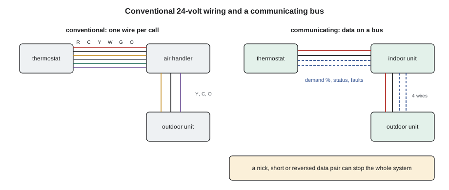
In a conventional system, a thermostat closes R to Y, W, G or O, and each wire carries one on-off call. In a communicating system, the thermostat, indoor unit and outdoor unit exchange digital messages: the thermostat sends a demand as a percentage, the indoor unit sets the blower airflow, the outdoor unit sets the compressor speed, and each reports its status and faults back. The bus usually uses four wires, two for 24-volt power and two for data, often labeled with numbers or letters by each manufacturer. Communicating equipment can set itself up automatically, display detailed faults on the thermostat and deliver much finer control, but components generally must be from the same manufacturer's communicating family, and the bus is sensitive to wiring faults that a 24-volt system would tolerate.
Ductless systems use a different arrangement. On many of them, the interconnecting cable between the outdoor and indoor units carries line voltage to power the indoor unit and a communication signal on a third conductor, all referenced to the same supply. That means the communication wire can be at a dangerous voltage. Treat every conductor in a ductless interconnect as live until you have verified otherwise, use meters rated for the circuit and follow the manufacturer's procedure for checking the signal, which often specifies a fluctuating DC voltage between two particular terminals.
Troubleshooting communication faults
Communication faults have a short list of usual causes, and checking them in order saves boards.
- Power: confirm 24 V between the power conductors at each device, under load.
- Wiring: a nick, a short to ground, a reversed data pair, a loose terminal or a splice made with the wrong connector.
- Noise: bus wiring run beside line-voltage cable or long unshielded runs where the manufacturer specifies separation or shielding.
- Configuration: a replaced board or thermostat that has not been set up for the system, or mismatched firmware versions.
- Termination and topology: some buses require a particular arrangement or termination; follow the manual.
Most manufacturers specify a voltage, or a range of fluctuating voltage, between the data conductors, and a resistance check of each conductor with power off and both ends disconnected. Measure from the thermostat end and from the equipment end, and look for differences.
ECM blowers and airflow settings
Communicating air handlers and many conventional ones use ECM blower motors programd for airflow rather than speed. On conventional equipment, the airflow for each mode is selected by taps, dip switches or a menu; on communicating equipment, the system sets it from the installer's configuration. RAC-220 showed how airflow affects superheat, subcooling and capacity. When a heat pump or air conditioner underperforms after a board or motor replacement, check that the airflow settings match the installation, because the replacement may have arrived with factory defaults.
Firmware, configuration and records
Boards and thermostats run software, called firmware, and manufacturers update it to fix faults and add features. Updates are installed through a service tool, an app or the thermostat. A replacement board may need the model number, capacity, airflow settings, accessory options and the system's refrigerant configured before it will run correctly. Write down the configuration of an existing system before replacing any board, photograph the dip switches and connectors, and record the firmware version. On A2L systems with refrigerant detection, as at the Lindqvists', the detection sensor and its mitigation settings are part of that configuration.
Finding the fault at the Lindqvists'
Theo started at the thermostat: 24 V across the power pair, but the data voltage was steady at zero instead of fluctuating within the manufacturer's range. At the air handler in the basement, the data pair showed the same thing. With power off and both ends disconnected, he checked each conductor for continuity and for shorts: the two data conductors were shorted together. Following the cable, he found where the renovation crew had stapled it to a joist, driving a staple through the jacket. He replaced the damaged section with a continuous run of the specified cable rather than splicing it, reconnected the bus and powered up. The system rediscovered itself within a minute, the thermostat cleared the fault and the heat pump started. Before leaving, Theo read the fault history: three communication faults, all since the renovation, and nothing else. He also checked the refrigerant detection system's status, which showed normal.
Using service tools and apps
Most manufacturers now offer a service tool, an app or a web portal that connects to their equipment by cable, Wi-Fi or Bluetooth. These tools show live sensor values, compressor frequency, valve steps and fan speeds, run test modes, read fault histories with time stamps, update firmware and save the configuration. They make diagnosis much faster, but they do not replace measurement. A displayed suction pressure comes from a transducer that may be wrong, and a displayed temperature comes from a thermistor that may be loose, so confirm key values with your own instruments before acting on them. Keep the tools updated, because new equipment models may not appear in old versions, and save a copy of each unit's data before and after any repair. When a customer's system is connected to the internet for remote monitoring, use only the owner's and manufacturer's approved access methods, as lesson 10 explains.
When the board really is the fault
Boards do fail, most often from lightning and power surges, water from a leaking coil or roof, overheating in a hot cabinet, and short circuits in the wiring they feed, such as a chafed thermostat wire that burns a trace or a fuse. A board is the likely fault only when its inputs are correct, its power is correct and it still gives the wrong output: for example, when 24 V reaches the board, every sensor reads correctly and the board commands the compressor on, but its relay never closes. Before installing a replacement, find out why the original failed, or the new board may fail the same way. Check for burned traces, water stains and failed fuses, and measure the current of every coil and load the board drives.
Common mistakes
MistakeResetting power before reading the fault code.
InsteadRead and record the active code and history first.
MistakeReplacing a board because of a communication fault.
InsteadCheck power, wiring, noise and configuration first.
MistakeTreating a ductless interconnect's communication wire as low voltage.
InsteadTreat all interconnect conductors as live and follow the manufacturer's test procedure.
MistakeWorking on an inverter board as soon as power is off.
InsteadWait for the DC bus to discharge and verify it with a meter.
MistakeInstalling a replacement board without configuring it.
InsteadRecord the old configuration and set up the new board to match the installation.
Summary and key terms
- Integrated boards run sequences and report faults by flashes, codes or thermostat messages.
- Variable-speed systems rely on many sensors; use test modes and service displays.
- Ratiometric transducers output a fixed fraction of supply voltage; check them against a gauge.
- Communicating systems exchange data on a bus that is sensitive to wiring faults and configuration.
- Ductless interconnect wiring often carries line voltage on the communication conductor.
- Configuration, airflow settings and firmware are part of every board replacement.
- Integrated control board
- A circuit board that runs an appliance's sequence, safeties and diagnostics.
- Fault code
- A number or message a control reports to identify a fault.
- Inverter board
- A board that converts AC to DC and back to variable-frequency AC to drive a compressor.
- Pressure transducer
- A sensor that outputs a voltage or current proportional to pressure.
- Ratiometric output
- A sensor output that is a fixed fraction of its supply voltage.
- Communicating system
- A system in which thermostat, indoor and outdoor units exchange digital messages.
- Firmware
- The software stored in a control board or thermostat.
- Test mode
- A manufacturer's service mode that runs equipment at fixed conditions for checks.
Practice problems
Work each problem on paper first, then reveal the answer to check.
A 0.5–4.5 V transducer rated 0 to 500 psi reads 2.5 V at a 5.0 V supply. What pressure does it indicate?
Show answer
250 psi.
The board shows a suction pressure 25 % lower than a calibrated gauge. What should be done?
Show answer
Check the transducer's supply and output, then replace the transducer if it is out of tolerance.
A communicating thermostat shows a communication fault after a renovation. What is the first likely cause to check?
Show answer
Damage to the bus wiring.
Why must you wait before touching an inverter board after shutting off power?
Show answer
The DC bus capacitors store a dangerous charge.
Lesson quiz · 5 questions
Score 60% or more to complete this lesson.
Create a free account to save your progress, take quizzes and earn a certificate.