
RAC-230 · Lesson 3 of 12 · 17 min
Operating controls: thermostats, pressure controls and pump-down
Rosa, who owns the second of Northfield's two restaurant customers, had a new walk-in cooler installed in her kitchen over the summer by a general contractor's refrigeration sub. It held temperature, but every morning the compressor started with a rattle, and twice in September its internal overload had tripped right after start. Dana suspected liquid refrigerant migrating to the compressor overnight. The condensing unit sat on the roof, where the night air was colder than the kitchen, and the system had a simple thermostat that just started and stopped the compressor. "No pump-down, no crankcase heater," she said. "We're going to set this one up properly." Theo would do the controls; Raj would handle the refrigeration work.
Operating controls are the controls that run equipment in normal service: they start, stop and stage compressors, fans, valves and heaters to hold the conditions the customer wants. Safety controls, which protect people and equipment and are covered in lesson 4, override them. This lesson covers the operating controls of refrigeration and air conditioning systems: temperature controls, pressure controls used as operating controls, pump-down and pump-out, condenser fan cycling and staging.
Temperature controls in refrigeration
A refrigeration system can be controlled by temperature directly or by pressure as a stand-in for temperature. A thermostat in the box measures the air and is the most direct method; it may be a mechanical bulb-type control, a digital thermostat or a full case controller. In the simplest arrangement, the thermostat contact is wired in series with the compressor contactor coil, so the compressor runs when the box calls. This is easy to install and understand, but when the compressor stops, the low side is full of refrigerant, and if the condensing unit is colder than the evaporator, refrigerant vapor migrates to the compressor crankcase and condenses there, diluting the oil. At the next start, the oil foams, the bearings run short of lubrication and liquid can reach the cylinders or scrolls.
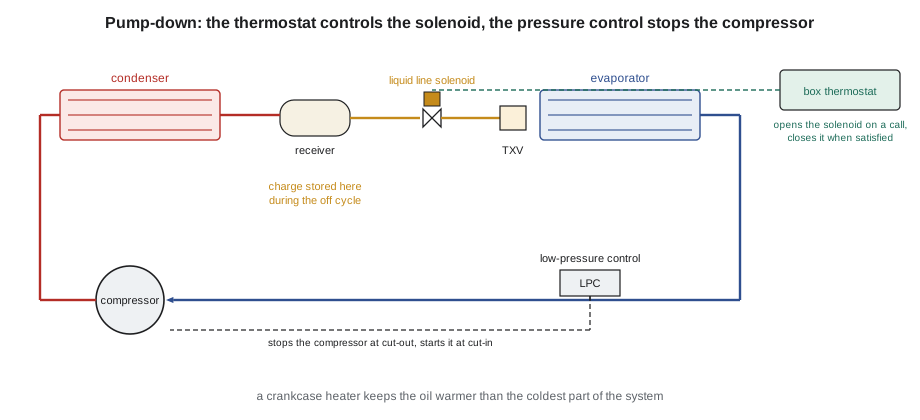
The better arrangement for most commercial systems is pump-down. The thermostat controls a liquid line solenoid valve instead of the compressor. When the box is satisfied, the solenoid closes and the compressor keeps running, pumping refrigerant out of the evaporator and suction line into the condenser and receiver. As the low side empties, the suction pressure falls until a low-pressure control opens and stops the compressor. When the box warms and the thermostat calls again, the solenoid opens, refrigerant rushes into the evaporator, the suction pressure rises above the low-pressure control's cut-in, and the compressor starts. The refrigerant spends the off cycle stored in the receiver, not in the evaporator or compressor.
Pump-down, pump-out and crankcase heaters
There are two versions. In continuous or recycling pump-down, the low-pressure control both stops and restarts the compressor directly. If the solenoid valve leaks slightly, or the compressor's valves let gas back into the low side, the suction pressure creeps up during the off cycle until it reaches the cut-in, and the compressor briefly restarts to pump down again. Occasional short pump-down runs are a sign of exactly that, and many technicians use them as a diagnostic: a system that pumps down every few minutes with the thermostat satisfied has a leaking solenoid or compressor valves. In single pump-down, also called pump-out, a relay or the controller locks the compressor out after one pump-down until the thermostat calls again, so a leaking solenoid cannot cause short cycling. The trade-off is that a refrigerant leak-back is then not cleared until the next call.
Pump-down reduces migration but does not eliminate it, because some refrigerant remains in the low side and in the compressor shell. A crankcase heater, a belly-band or insert heater that keeps the oil warmer than the coldest part of the system, keeps refrigerant from condensing in the oil. Many compressor manufacturers require crankcase heaters on outdoor units in cold climates or above a certain charge, and the heater must be energized long enough before start-up after a long shutdown, often many hours, for the oil to drive off any refrigerant. A crankcase heater is checked by its current draw and by touch: the bottom of the compressor shell should be noticeably warm during the off cycle.
Low-pressure controls
A low-pressure control, often abbreviated LPC, is a pressure switch connected to the suction line. Its contacts open on a fall in pressure to the cut-out and close on a rise to the cut-in. Mechanical controls have two adjustments, which may be labeled range and differential, or cut-in and cut-out; on range-differential controls, the range screw sets the cut-in and the differential screw sets how far below it the control cuts out. Electronic controllers use a pressure transducer and set the values in software. In refrigeration, a low-pressure control has three possible jobs, and the settings depend on which one it is doing.
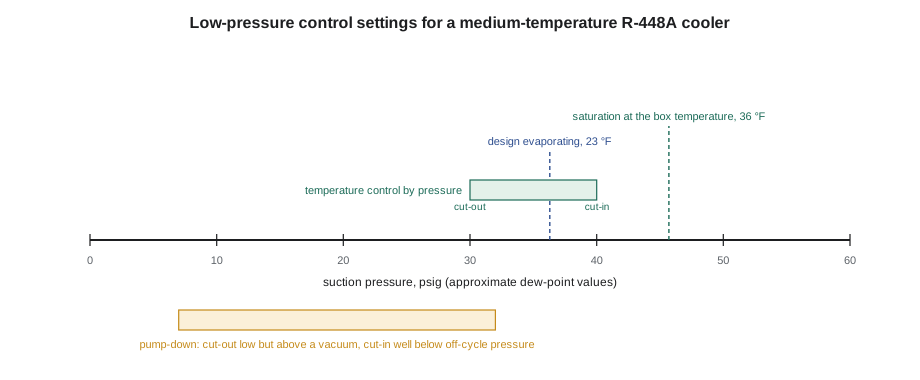
- Pump-down control: stops the compressor at the end of pump-down. The cut-out is set low, but safely above a vacuum, and the cut-in is set so the compressor restarts promptly when the solenoid opens but not from minor leak-back.
- Temperature control by pressure: on some small coolers, the low-pressure control is the only temperature control. The cut-in corresponds to the saturation pressure at a temperature close to the box temperature, and the cut-out to the evaporating temperature at which the box is cold enough. Because the coil warms to near box temperature during the off cycle, the cut-in also ensures off-cycle defrost on medium-temperature coolers.
- Low-pressure safety: protects against loss of charge or a frozen coil, usually with a manual or automatic reset and lower settings. Lesson 4 covers it.
Settings are found from the refrigerant's pressure-temperature relationship. For a blend with glide, use the dew point, because the control senses vapor pressure in the suction line. Settings should also allow for the pressure drop in the suction line between the evaporator and the control, which on long rooftop runs can be the equivalent of 2 to 4 °F.
# Low-pressure control settings from approximate R-448A dew-point values (illustrative; always use the manufacturer's data)
DEW = [(-13, 6.5), (-4, 13.1), (5, 20.3), (14, 27.6), (23, 36.3), (32, 45.7), (41, 56.6)]   # (saturation temperature F, pressure psig)

def p_at(t):
    for (t1, p1), (t2, p2) in zip(DEW, DEW[1:]):
        if t1 <= t <= t2:
            return p1 + (p2 - p1) * (t - t1) / (t2 - t1)
    raise ValueError("outside table")

box, td, line_drop = 36.0, 12.0, 2.0      # box air, coil TD and suction line drop, all in F or F
evap = box - td
print(f"design evaporating temperature: {evap:.1f} F")
# temperature control by pressure: cut in near box temperature, cut out a few degrees below design evaporating
cut_in = p_at(box - 2.0 - line_drop)
cut_out = p_at(evap - 5.0 - line_drop)
print(f"temperature control by pressure: cut-in about {cut_in:.0f} psig, cut-out about {cut_out:.0f} psig")
# pump-down control: cut out low but above a vacuum, cut in well below the off-cycle low-side pressure
pd_out = 7
pd_in = p_at(evap - 5.0)
print(f"pump-down: cut-out about {pd_out} psig, cut-in about {pd_in:.0f} psig (differential {pd_in - pd_out:.0f} psi)")design evaporating temperature: 24.0 F temperature control by pressure: cut-in about 46 psig, cut-out about 30 psig pump-down: cut-out about 7 psig, cut-in about 32 psig (differential 25 psi)
The program follows the reasoning a technician uses with a P-T chart. With the box at 36 °F and a coil selected for a 12 °F TD, the design evaporating temperature is about 24 °F. For temperature control by pressure, the cut-in sits near the saturation pressure of the box temperature, so the coil has warmed and cleared any frost before the compressor restarts, and the cut-out sits a few degrees below the design evaporating temperature. For pump-down, the cut-out is low but above a vacuum, and the cut-in is high enough that ordinary leak-back does not reach it but low enough that the compressor restarts as soon as the solenoid opens. Final settings are confirmed by watching several cycles and checking box temperature, run time and starts per hour.
Condenser fan cycling and head pressure
Air-cooled condensers sized for summer can drive the head pressure far too low in cold weather, starving the metering device. RAC-210 described head pressure control valves that flood the condenser. A simpler method on small systems is fan cycling: a high-side pressure control, or a temperature control on the liquid line or condenser, switches one or more condenser fans off when the head pressure falls below a cut-out and back on at a higher cut-in. On multi-fan condensers, fans are staged one at a time, and many newer condensing units use a variable-speed fan driven by a head pressure transducer instead. Fan cycling alone is usually not enough for very low ambient conditions; manufacturers often combine it with a flooding valve or variable-speed fan, and wind across a rooftop unit can defeat fan cycling entirely.
Rosa's walk-in had a single-fan condensing unit on the roof. Raj noted that it already had a fan-cycling control set by the factory, but no head pressure valve. Because the cooler ran all winter, he recommended adding one, and Dana quoted it separately.
Staging and multi-stage thermostats
Larger systems often have more capacity than the load needs most of the time. Staging divides it into steps. A two-stage cooling thermostat closes Y1 first and Y2 only when the space keeps warming or the first stage has run for a set time; a two-stage heat pump thermostat adds auxiliary heat (W2) as a further stage. Rooftop units with two compressors run one or both. Each stage has its own differential, and stages are separated by an interstage differential, so the second stage starts only if the space moves further from setpoint. Time delays between stages stop two compressors from starting together and loading the electrical supply.
- Interstage differential: the difference between the points at which stage one and stage two turn on.
- Minimum on and off times: protect compressors from short cycling, often a few minutes each.
- Outdoor temperature lockouts: on heat pumps, a balance-point or lockout setting may stop the compressor or allow auxiliary heat based on outdoor temperature.
- Humidity control: humidistats or dehumidification modes lower blower speed or add reheat to remove more moisture, as at the dental clinic in RAC-110.
Setting up the walk-in
Raj installed a liquid line solenoid valve just ahead of the TXV, with its coil rated for the controller's voltage, and a strap-on crankcase heater rated by the compressor manufacturer. Theo rewired the box thermostat to the solenoid coil and moved the compressor contactor coil to a new adjustable dual-pressure control, wired in series with the existing high-pressure safety. With the solenoid closed by hand at the thermostat, he watched the pump-down: the suction gauge fell steadily, and the control opened at the cut-out he had set. Over the next twenty minutes the pressure rose by only a psi or two, well short of the cut-in, so the solenoid and compressor valves were tight. When he let the thermostat call, the solenoid opened with an audible click, the suction pressure jumped above the cut-in within seconds and the compressor started without any rattle.
Before leaving, Theo checked the crankcase heater current, labeled the new control with its settings and the date, and set the digital thermostat's minimum off time to three minutes. The next morning, Rosa sent Dana a message: the rattle was gone.
Checking a pressure control
A pressure control's scale is only a guide, so its actual settings must be checked with gauges. Connect a gauge to the same line the control senses, as close to the control as possible, and watch the pressure at which the contacts open and close while the system pumps down or the condenser fans cycle. Many technicians use a temporary manifold arrangement on the bench, applying nitrogen pressure slowly to the control and watching a meter on its contacts, which is a reliable way to set a replacement control before installing it. Write the measured cut-in and cut-out on a label on the control. A control whose bellows has cracked or whose capillary has leaked will not hold settings and must be replaced, and its capillary must be routed so it cannot rub or vibrate against other lines.
Common mistakes
MistakeWiring the thermostat to the compressor on an outdoor condensing unit without pump-down or a crankcase heater.
InsteadUse pump-down with a liquid line solenoid and a crankcase heater where migration is possible.
MistakeIgnoring frequent short pump-down runs.
InsteadTreat them as a sign of a leaking solenoid or compressor valves and investigate.
MistakeSetting a low-pressure control from the bubble point of a blend.
InsteadUse the dew point, because the control senses suction vapor pressure.
MistakeSetting a pump-down cut-out into a vacuum.
InsteadKeep the cut-out above atmospheric pressure so air and moisture cannot be drawn in at any leak.
MistakeStarting a compressor after a long shutdown with the crankcase heater just switched on.
InsteadEnergize the heater for the time the manufacturer specifies before start-up.
Summary and key terms
- Operating controls run equipment in normal service; safety controls override them.
- Pump-down stores the charge in the receiver during the off cycle and reduces migration.
- Single pump-down prevents short cycling from a leaking solenoid; recycling pump-down reveals it.
- Low-pressure control settings come from the dew-point P-T values, allowing for suction line drop.
- Fan cycling and variable-speed fans hold head pressure up in cold weather.
- Staging uses interstage differentials and time delays to match capacity to load.
- Pump-down
- Closing the liquid line solenoid and running the compressor until a low-pressure control stops it, storing refrigerant in the receiver.
- Liquid line solenoid valve
- An electrically operated valve that opens or closes the liquid line.
- Crankcase heater
- A heater that keeps compressor oil warm during the off cycle to prevent refrigerant migration.
- Migration
- Movement of refrigerant to the coldest part of a system during the off cycle.
- Cut-in
- The value at which a control closes its contacts.
- Cut-out
- The value at which a control opens its contacts.
- Fan cycling control
- A control that switches condenser fans off and on to hold head pressure in cold weather.
- Interstage differential
- The difference between the turn-on points of successive stages.
Practice problems
Work each problem on paper first, then reveal the answer to check.
A walk-in compressor pumps down every eight minutes while the thermostat is satisfied. What is likely?
Show answer
A leaking liquid line solenoid or leaking compressor valves.
Why is the dew point used for low-pressure control settings on R-448A?
Show answer
The control senses suction vapor pressure.
A cooler uses its low-pressure control as the temperature control. Why is the cut-in set near the saturation pressure of the box temperature?
Show answer
So the coil warms and clears frost before the compressor restarts.
What does single pump-down prevent?
Show answer
Short cycling caused by leak-back during the off cycle.
Lesson quiz · 5 questions
Score 60% or more to complete this lesson.
Create a free account to save your progress, take quizzes and earn a certificate.