
RAC-230 · Lesson 2 of 12 · 19 min
Temperature sensors and how to check them
The seniors' residence called about the second-floor corridor. Residents said it was stuffy and too warm, and the building automation screen in the maintenance office showed the make-up air unit discharging air at 61 °F, below its 64 °F setpoint, with the gas heat at full fire. Wes Kaminski, the maintenance supervisor, had already reset the controller twice. Raj brought Theo along. Before touching the controller, Raj slid a calibrated probe thermometer into a test port in the discharge duct, a few centimeters from the unit's own sensor. It read 66 °F, and climbing. "The unit is doing exactly what it's told," Raj said. "It's being told the wrong temperature."
Every control decision starts with a sensor. A thermostat cannot be better than the bulb or thermistor that feeds it, and a building automation system with a thousand points is only as good as its worst sensor. This lesson covers the temperature sensors found in HVAC-R equipment, how each one works, what can go wrong and how to check them quickly and reliably. Pressure transducers and other sensors used in electronic controls appear in lessons 6 and 7.
Bimetal elements
A bimetal element is two strips of metals with different rates of thermal expansion bonded together. When the temperature changes, one metal grows more than the other and the strip bends. Wound into a coil or formed into a snap disc, it can open or close a contact directly. Bimetal elements are found in older room thermostats, in limit switches on furnaces and electric heaters, in the defrost termination thermostats clipped to evaporator coils, in fan delay switches and in the internal overloads of compressors and motors. A snap disc has a fixed cut-in and cut-out marked on its body, such as L140-113, meaning it opens on a temperature rise at the first value and closes again on a fall to the second.
Bimetal devices are checked by temperature and continuity. Clip a thermocouple next to the disc, change its temperature with the system or a heat gun used carefully, and confirm that it opens and closes within a few degrees of its rating. A disc that has been overheated may stick open or drift. Because a snap disc senses the temperature of whatever it touches, it must be clamped firmly to clean metal; a defrost termination disc hanging loose in the air, as on the restaurant freezer in RAC-210, ends defrost long before the coil is clear.
Thermostatic bulbs
Many mechanical refrigeration controls use a bulb, capillary and bellows or diaphragm filled with a temperature-sensitive charge, the same principle as the TXV bulb in RAC-220. As the bulb warms, the charge's pressure rises and pushes the bellows against an adjustable spring, operating a snap-acting switch. Walk-in and reach-in thermostats, freeze protection thermostats on coils and low-limit controls on air handlers often use this arrangement. Three types of charge are common.
- Vapor charge: a small amount of liquid that is completely vaporized above a certain temperature. The control responds at the coldest point of its system, but the bulb must be the coldest part, or the charge condenses at the head or capillary instead.
- Liquid charge: the system is filled with liquid, so the bellows responds to volume change. These work wherever the head sits but have a limited range.
- Cross-ambient or averaging charge: designed so the control responds to the coldest point along a long capillary, as in a freeze-stat strung across the face of a coil.
When a bulb loses its charge, the bellows sees only spring pressure, as if the bulb were extremely cold. On a cooling thermostat the result is that the contacts stay open and the compressor never runs. That is exactly what happened in the restaurant's dessert reach-in the same week: the capillary had rubbed through on a sharp shelf bracket, the box warmed to 54 °F, and turning the dial to its coldest setting did nothing. On a freeze-stat, a lost charge usually trips the control and shuts the air handler down, which is the safe direction. A capillary must never be kinked, cut, shortened or used as a tie-down point.
Thermistors
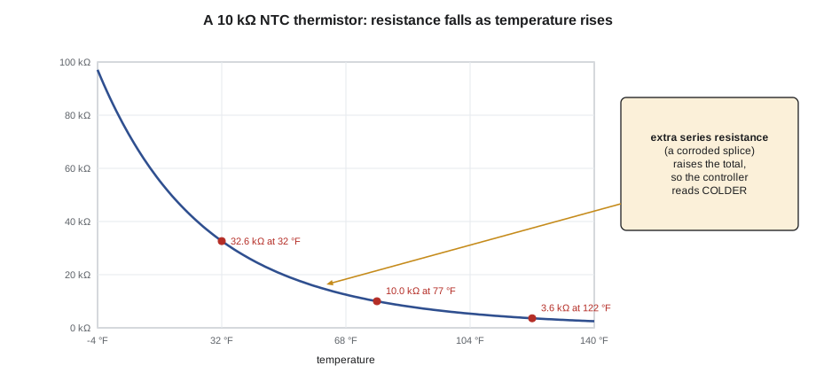
A thermistor is a small bead of semiconductor material whose resistance changes strongly with temperature. Nearly all HVAC-R thermistors are NTC types, negative temperature coefficient, meaning their resistance falls as they warm. They are cheap, small and sensitive, and they are used for coil, suction line, discharge line, outdoor air, return air and supply air sensing on almost every electronic control board, case controller and inverter unit. A thermistor is described by its resistance at 77 °F, most often 10 kΩ, and by its curve. Two common 10 kΩ curves, often called Type II and Type III, differ by several percent away from 77 °F, and manufacturers also use 2.2 kΩ, 5 kΩ, 15 kΩ and 20 kΩ parts. A replacement must have the same curve as the original, not just the same resistance at 77 °F.
The relationship between resistance and temperature is strongly non-linear. Manufacturers publish tables, and controllers convert resistance to temperature with a lookup table or the Steinhart-Hart equation, where T is the absolute temperature in kelvin, R is the resistance and A, B and C are constants for the particular thermistor:
import math
# Fit Steinhart-Hart constants to three points from a 10 kohm thermistor table (approximate Type II style values)
pts = [(0.0, 32650.0), (25.0, 10000.0), (50.0, 3603.0)]   # (temperature C, resistance ohm)
L = [math.log(r) for _, r in pts]
Y = [1.0 / (t + 273.15) for t, _ in pts]
g2 = (Y[1] - Y[0]) / (L[1] - L[0]); g3 = (Y[2] - Y[0]) / (L[2] - L[0])
C = (g3 - g2) / (L[2] - L[1]) / (L[0] + L[1] + L[2])
B = g2 - C * (L[0] ** 2 + L[0] * L[1] + L[1] ** 2)
A = Y[0] - (B + C * L[0] ** 2) * L[0]
print(f"A = {A:.4e}, B = {B:.4e}, C = {C:.4e}")

def temp(r_ohm):
    lr = math.log(r_ohm)
    return 1.0 / (A + B * lr + C * lr ** 3) - 273.15

def show(t_c):
    return f"{t_c * 1.8 + 32:.1f} F"

true_r = 13200.0                 # sensor resistance at the actual discharge air temperature
print("sensor alone:", show(temp(true_r)))
for splice in (500.0, 1000.0, 2000.0):
    print(f"with {splice:.0f} ohm of extra resistance in the circuit: controller reads {show(temp(true_r + splice))}")
print("an open circuit reads as extremely cold; a short circuit reads as extremely hot")A = 1.1253e-03, B = 2.3472e-04, C = 8.5631e-08 sensor alone: 65.8 F with 500 ohm of extra resistance in the circuit: controller reads 64.3 F with 1000 ohm of extra resistance in the circuit: controller reads 62.9 F with 2000 ohm of extra resistance in the circuit: controller reads 60.3 F an open circuit reads as extremely cold; a short circuit reads as extremely hot
The program shows why Raj suspected the wiring. Resistance added in series with an NTC thermistor makes the controller think the air is colder than it is. About 2 kΩ of extra resistance at a corroded splice makes a sensor at 65.8 °F read about 60.3 °F, and the controller fires more heat to correct a problem that does not exist. Open circuits read as very cold and short circuits as very hot, which is why most controllers flag readings far outside the sensor's range as sensor faults rather than temperatures.
RTDs
A resistance temperature detector, or RTD, is a coil or film of platinum, nickel or another metal whose resistance rises almost linearly with temperature. Platinum RTDs are the most common: a Pt100 has 100 Ω and a Pt1000 has 1000 Ω at 32 °F, and the standard curve rises by about 0.385 % of that value per kelvin. RTDs are more stable and more accurate than thermistors, so they are used where accuracy matters: chilled-water and hot-water supply and return sensors for energy calculations, chiller leaving water sensors and process temperatures. Accuracy classes are defined in international standards, with class A and class B the common grades.
RTDs are wired with two, three or four wires. With two wires, the resistance of the leads adds directly to the reading. For a Pt100, 1 Ω of lead resistance is about 2.6 K of error, while for a Pt1000 it is about a tenth of that, which is one reason Pt1000 sensors are popular for HVAC. Three-wire and four-wire connections let the transmitter measure and cancel the lead resistance. A sensor fed to a transmitter that converts it to a 4–20 mA signal is immune to lead resistance in the signal wiring, because the transmitter controls the current regardless of wire length.
# RTD reading and lead resistance error (standard platinum coefficient about 0.00385 per K)
ALPHA = 0.00385
def rtd_temp(r_measured, r0):
    return (r_measured / r0 - 1.0) / ALPHA

lead = 0.8        # total resistance of both leads, ohm (about 80 ft of small wire, out and back)
t_c = 6.7            # actual chilled-water temperature in C (44.0 F)
for r0, name in ((100.0, "Pt100"), (1000.0, "Pt1000")):
    r = r0 * (1 + ALPHA * t_c) + lead
    err = rtd_temp(r, r0) - t_c
print(f"{name}: two-wire reading is high by {err * 1.8:.2f} F with {lead} ohm of leads")Pt100: two-wire reading is high by 3.74 F with 0.8 ohm of leads Pt1000: two-wire reading is high by 0.37 F with 0.8 ohm of leads
Thermocouples
A thermocouple is a junction of two different metals that produces a small voltage depending on the temperature difference between the measuring junction and the meter's reference junction. Type K (chromel and alumel) is the common general-purpose type in service meters, and Type T (copper and constantan) is often preferred for low temperatures. Thermocouples are rugged and fast, which is why most technicians' clamp and pipe temperature probes use them. They are seldom used as permanent control sensors in HVAC-R, except in gas appliances, where a thermocouple or thermopile proves a pilot flame, a function covered in gas technician training rather than this course.
Where a sensor is placed
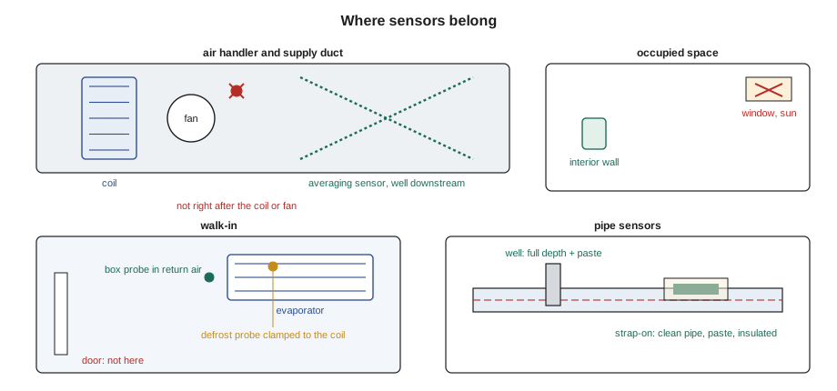
A perfectly accurate sensor in the wrong place still gives the controller the wrong information. Supply air sensors belong far enough downstream of coils and burners for the air to be mixed, often several duct diameters, or they should be averaging sensors strung across the duct. Return and space sensors must not be in sunlight, on exterior walls, above heat sources, in dead air corners or in a supply air jet. Box air sensors in walk-ins usually sit in the return air entering the evaporator, which represents the box, while coil sensors for defrost are clamped to a tube or fin location the manufacturer specifies. Pipe sensors in wells need heat-transfer paste and full insertion; strap-on pipe sensors need clean pipe, paste and insulation over them. Response time matters too: a sensor in a heavy well may lag the water by a minute or more, which affects how the loop can be tuned.
Checking a temperature sensor
Checking a sensor has three parts. First, compare the controller's reading with an independent, calibrated instrument placed at the same spot, with time to stabilize. A difference of more than about 2 °F on a comfort sensor, or less on a process or energy-metering sensor, is worth investigating. Second, if the readings disagree, isolate the sensor: disconnect it at the controller, measure its resistance and compare it with the manufacturer's table at the temperature your reference reads. Third, if the sensor is good, measure resistance at the controller with the sensor connected at the far end, to find wiring problems such as corrosion, loose terminals or damaged cable.
- Ice bath check: a slurry of crushed ice and water, well stirred, is very close to 32 °F and gives a quick check of both the reference instrument and many sensors.
- Never apply external voltage to a sensor while it is connected to a control board, and never megohm-test sensor wiring without disconnecting it from the board.
- Most controllers allow an offset or calibration value; use it only for small, documented corrections, never to hide a faulty sensor or bad wiring.
- Keep a record of the reference instrument's calibration date.
Finding the splice
At the residence, Raj had Theo disconnect the discharge sensor at the controller and measure the loop: 15.2 kΩ. At the sensor, with the wires lifted, the element alone read 13.2 kΩ, which the manufacturer's table put at about 65.8 °F, within a fraction of a degree of the probe in the same spot after the unit had been throttled back. The missing 2 kΩ was in a wire-nut splice above the corridor ceiling, where condensation from a poorly insulated duct had dripped for years and turned the copper green. Theo replaced the splice with a sealed, gel-filled connector, the reading came back to match the probe, and the gas valve modulated down within minutes. Raj removed an old −4 °F offset someone had programd into the controller years earlier to fight the same symptom, then had Theo check the reading against the probe again.
Wes asked whether the other sensors in the building could have the same problem. Raj suggested a simple test: on the building automation screens, compare each air handler's supply air reading with the mixed air and return air readings during a period with no heating or cooling. Any sensor that disagrees by more than a degree or so from what the physics says it should read deserves a visit. Lesson 11 returns to this idea of using trends to find faulty sensors.
Common mistakes
MistakeUsing a calibration offset to cover a wiring fault.
InsteadFind and fix the resistance in the wiring; use offsets only for small documented corrections.
MistakeReplacing a 10 kΩ thermistor with any other 10 kΩ part.
InsteadMatch the curve type and the manufacturer's part, not just the resistance at 77 °F.
MistakeChecking a sensor against the controller display alone.
InsteadCompare with a calibrated reference instrument at the same location.
MistakeLeaving a strap-on pipe sensor bare.
InsteadUse paste, clean pipe and insulation over the sensor.
MistakeKinking or shortening a thermostat capillary.
InsteadRoute it without sharp bends and secure it without crushing it.
Summary and key terms
- Bimetal discs and strips switch directly and must be clamped to what they sense.
- Thermostatic bulbs lose their charge if the capillary is damaged; a cooling thermostat then never calls.
- NTC thermistors fall in resistance as they warm; extra series resistance makes them read cold.
- RTDs are near-linear and stable; lead resistance matters for two-wire Pt100s.
- Sensor location and response time matter as much as accuracy.
- Check a sensor against a reference, then isolate the element, then test the wiring.
- NTC thermistor
- A sensor whose resistance falls as its temperature rises.
- RTD
- A resistance temperature detector, usually platinum, whose resistance rises nearly linearly with temperature.
- Pt1000
- A platinum RTD with 1000 ohms at the freezing point of water.
- Steinhart-Hart equation
- An equation relating a thermistor's resistance to its absolute temperature using three constants.
- Vapor-charged bulb
- A thermostatic bulb whose charge is fully vaporized above a set temperature, so the control responds at the coldest point.
- Snap disc
- A bimetal disc that snaps open or closed at fixed temperatures.
- Averaging sensor
- A long sensing element strung across a duct or coil to measure an average temperature.
- Thermocouple
- A junction of two metals that produces a small voltage depending on temperature.
Practice problems
Work each problem on paper first, then reveal the answer to check.
A 10 kΩ NTC thermistor reads 10 kΩ. What temperature is it near?
Show answer
About 77 °F.
A space sensor reads 5 °F colder than a reference beside it, and the sensor element tests correctly. Where should you look next?
Show answer
At the wiring and terminals for extra resistance.
A cooling thermostat with a vapor-charged bulb will not call even at its coldest setting, and the box is warm. What should you suspect?
Show answer
A lost bulb charge from a damaged capillary.
Why is a Pt1000 less affected by lead resistance than a Pt100?
Show answer
The same lead resistance is a tenth of the percentage change.
Lesson quiz · 5 questions
Score 60% or more to complete this lesson.
Create a free account to save your progress, take quizzes and earn a certificate.