
RAC-130 · Lesson 9 of 12 · 20 min
Three-phase motors, ECMs and variable-frequency drives
At the seniors' residence, Raj showed Theo three generations of motors in one mechanical room. The oldest was a 15-horsepower chilled water pump motor, connected straight to the 480-volt supply through a starter: it ran at full speed whenever it ran. Beside it, a newer pump of the same size was fed through a variable-frequency drive mounted on the wall, its display reading 47.2 hertz and 11.6 amperes. Upstairs, the corridor ventilation unit had been retrofitted with an electronically commutated fan motor the size of a dinner plate. "Same job, three ways of doing it," Raj said. "The pump on the drive uses maybe half the energy of the old one for the same water. But the drive and the ECM both have electronics that can hurt you after the power is off, and they fail in different ways."
This lesson covers the larger and newer motors technicians meet: three-phase induction motors, their nameplates, rotation and protection; electronically commutated motors (ECMs); and variable-frequency drives (VFDs), including the inverter drives in ductless heat pumps. It also covers the safety precautions for electronic drives.
Three-phase induction motors
A three-phase induction motor has three sets of windings in its stator, one for each phase. Because the three phase currents peak one after another, the magnetic field they create rotates around the stator smoothly, with no need for a start winding, capacitor or relay. The field induces currents in the rotor, usually a squirrel-cage rotor of aluminum or copper bars joined by end rings, and those currents create the rotor's own magnetic field, which follows the stator's rotating field. Three-phase motors are simple, rugged, efficient and self-starting, and they are used for compressors, pumps and fans above a few horsepower.
Like single-phase motors, their speed is set by frequency and the number of poles, with a few percent slip under load. Reversing any two of the three supply leads reverses the rotating field and the motor's direction. That is useful for fans and pumps, which must turn the right way, and critical for scroll compressors, as Lesson 4 described.
When a three-phase motor starts directly across the line, it draws a locked-rotor current typically about five to seven times its full-load current, for a second or two until it reaches speed. Large motors may use reduced-voltage starting, such as a soft starter that ramps up the voltage electronically, or part-winding starting on some chiller compressors, to limit the dip in building voltage.
Reading a motor nameplate
| Nameplate item | Meaning |
|---|---|
| HP or kW | Rated mechanical output power at the shaft |
| Volts | Rated voltage, such as 460 V for a 480-volt system or 208-230/460 V for dual-voltage motors |
| FLA | Full-load amperes at rated voltage and output |
| RPM | Speed at full load, a little below synchronous speed |
| SF | Service factor: a motor with SF 1.15 can carry 15 percent overload continuously, at higher temperature |
| Code letter | Locked-rotor kVA per horsepower, giving the starting current |
| Insulation class | Temperature rating of the winding insulation, such as class F or H |
| Phase, Hz | Number of phases and supply frequency |
Dual-voltage motors have nine leads, or more, that are connected one way for the low voltage and another way for the high voltage; the connection diagram is on the nameplate or inside the terminal box cover. Connecting a motor for the wrong voltage either overheats it within minutes or leaves it unable to develop its torque.
Electrical tests on a three-phase motor compare the three phases. With the power locked out and the motor disconnected, the resistances of the three windings should be equal, within a few percent, and there should be no continuity to the frame; a megohmmeter checks insulation. With the motor running, the three line currents should be close to each other and at or below the nameplate FLA, and the three line voltages balanced within about 2 percent.
Single-phasing
If one supply phase is lost, for example because one fuse has blown or a contactor pole has burned open, a three-phase motor is said to be single-phasing. A stopped motor will not start: it hums, draws locked-rotor current and trips its overloads. A motor that was already running may keep turning on the two remaining phases, but its current in those two phases rises sharply, often to well above the nameplate, and it overheats quickly. A clamp reading that shows normal or high current in two lines and zero in the third is the sign. Overload relays sensing all three phases and phase monitors that open the control circuit on a lost or reversed phase protect against it.
When a three-phase motor fails with a burnt winding, the pattern of damage often shows whether single-phasing was the cause: two phases burnt and one untouched. Replacing the motor without finding the blown fuse, the bad contactor pole or the loose connection that caused it leads to a second failure.
Electronically commutated motors
An electronically commutated motor, ECM, is a brushless DC motor with a permanent-magnet rotor and a built-in electronic control module. The module converts the AC supply to DC and then switches current through the stator windings in sequence, sensing the rotor's position so that the field always pulls the rotor around. Because the magnets do not need induced current, ECMs are much more efficient than shaded-pole and PSC motors, especially at reduced speed, and their speed can be varied over a wide range. They are used in furnace and air handler blowers, condenser fans, and evaporator fans in walk-in coolers and display cases.
There are two common kinds. A constant-torque ECM has several speed taps, like a multi-speed PSC motor, energized with 24 volts or line voltage; each tap selects a programd torque. A constant-airflow ECM is programd by the equipment manufacturer and receives commands from the furnace or air handler control board; it adjusts its torque to keep a set airflow as filters load and duct pressure changes. Both have line voltage connected to the motor all the time, and the speed is selected by low-voltage signals. Switching the line voltage on and off to control an ECM, as is done with a PSC motor, can damage it.
Troubleshooting an ECM starts with the inputs: line voltage at the motor's power connector, a good ground, and the control signal at the low-voltage connector when the motor should run. If both are correct and the motor does not run, the module or motor has failed. Manufacturers' diagnostic tools can test some motors. The module holds charged capacitors, so after removing power, wait before unplugging connectors, as the manufacturer instructs; never unplug the power connector while the motor is energized, because the arc damages the pins. Replacement modules for constant-airflow motors must carry the correct program for the equipment model.
Variable-frequency drives
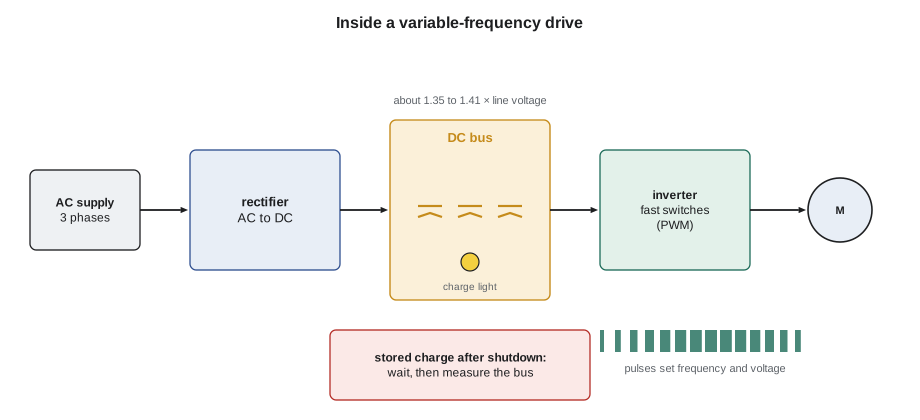
A variable-frequency drive, VFD, runs a standard induction motor at variable speed by changing the frequency of its supply. Inside, a rectifier converts the incoming AC to DC; a bank of large capacitors on the DC bus smooths it; and an inverter of fast transistor switches turns the DC back into AC by switching on and off thousands of times a second, a technique called pulse-width modulation. By changing the pattern of switching, the drive produces an output whose frequency, and voltage in proportion, can be set anywhere from a few hertz to above 60. The motor's speed follows the frequency.
The DC bus voltage is about 1.35 to 1.41 times the supply line voltage: roughly 325 to 340 volts DC on a 240-volt supply, and 650 to 680 volts DC on a 480-volt supply. Those capacitors can hold a lethal charge for minutes after the supply is opened, which is why drives carry a label stating the waiting time and many have a bus-charge light. Before working inside a drive or on its motor leads, lock out the supply, wait at least the stated time, then measure the DC bus at the drive's terminals with a meter rated for the voltage and confirm that it has fallen to a safe level. A dark charge light is not proof.
The output of a drive is not a smooth sine wave but a series of fast pulses, so ordinary meters may read it wrongly. Many true-RMS clamp meters have a low-pass filter or VFD mode for measuring drive output. Megohmmeter tests must never be done with the drive connected; disconnect the motor leads at the drive first.
Why drives save energy
Pumps and fans follow the affinity laws: flow is proportional to speed, pressure to the square of speed, and power to the cube of speed. A pump running at 80 percent speed delivers about 80 percent of the flow but needs only about half the power. Without a drive, flow is reduced by throttling a valve or a damper, which wastes the extra energy as pressure drop. That is why the residence's newer pump uses so much less energy than the old one for the same job.
# Synchronous speed, slip, affinity laws and DC bus voltage
f, poles, nameplate_rpm = 60, 4, 1760
ns = 120 * f / poles
print(f"synchronous speed {ns:.0f} rpm, slip {100 * (ns - nameplate_rpm) / ns:.1f} %")

full_kw = 11.2                        # pump input at 60 Hz (about 15 hp motor)
for hz in (60, 54, 47.2, 40):
    ratio = hz / 60
    print(f"{hz:5.1f} Hz: flow {ratio:4.0%}, head {ratio**2:4.0%}, power about {full_kw * ratio**3:4.1f} kW")

for line_v in (240, 480):
print(f"DC bus on a {line_v} V supply: about {1.35 * line_v:.0f} to {1.414 * line_v:.0f} V DC")synchronous speed 1800 rpm, slip 2.2 % 60.0 Hz: flow 100%, head 100%, power about 11.2 kW 54.0 Hz: flow 90%, head 81%, power about 8.2 kW 47.2 Hz: flow 79%, head 62%, power about 5.5 kW 40.0 Hz: flow 67%, head 44%, power about 3.3 kW DC bus on a 240 V supply: about 324 to 339 V DC DC bus on a 480 V supply: about 648 to 679 V DC
At 47.2 hertz, the frequency on the drive's display, the pump moves about 79 percent of its full flow while drawing a little under half its full-speed power. The real saving is somewhat smaller because of system pressure requirements and drive losses, but it is still large. The affinity laws are the reason drives are now standard on new pumps, cooling tower fans and air handler supply fans.
Worked problem
How much does the drive save?
The old constant-speed pump draws 11.2 kW for 4,000 hours a year. The new pump, on a drive, averages 50 Hz over the same hours. Using the affinity laws and ignoring drive losses, estimate the energy saved per year.
Show solution
- \[P_{50} = 11.2 \times \Big(\frac{50}{60}\Big)^3 \approx 11.2 \times 0.579 \approx 6.5\ \text{kW}\]
- \[E_{\text{saved}} = (11.2 - 6.5) \times 4000 \approx 18\,800\ \text{kWh per year}\]
Answer: Roughly 19,000 kWh a year, before drive losses of a few percent and any minimum-pressure limits in the system. Estimates like this are how building owners decide whether a drive retrofit pays for itself.
Inverter compressors
The attic ductless heat pump that Northfield installed last spring uses the same idea inside the outdoor unit. Its compressor is driven by an inverter board, which converts the 240-volt supply to DC and then to a variable-frequency supply for a permanent-magnet compressor motor, varying its speed to match the load instead of cycling on and off. Variable-speed compressors give steadier temperatures and better efficiency, especially at part load and in cold-climate heat pumps.
The inverter board stores energy in its DC bus capacitors just as a VFD does, often with a waiting time of several minutes printed on the board or cover. Service manuals give the test points and voltages for the DC bus and the compressor outputs, and most inverter units report faults with error codes on a display or a flashing LED. Inverter compressors are not tested like a single-phase compressor with C, S and R terminals: their three terminals are tested for equal winding resistance and insulation to ground, like a three-phase motor, with the board disconnected.
Common mistakes
MistakeSwitching line voltage on and off to control an ECM.
InsteadLeave line voltage on and control the speed through its low-voltage inputs.
MistakeOpening a VFD and touching the bus because the display is dark.
InsteadLock out, wait the stated time and measure the DC bus before touching anything.
MistakeMegohm-testing a motor while it is still connected to its drive.
InsteadDisconnect the motor leads at the drive first.
MistakeReplacing a burnt three-phase motor without checking the fuses and contactor poles.
InsteadFind the cause of single-phasing, or the new motor will fail too.
MistakeTesting an inverter compressor's terminals as C, S and R.
InsteadTreat them as three equal windings, as for a three-phase motor.
Summary and key terms
- Three-phase induction motors are self-starting; swapping two leads reverses them.
- Nameplates give voltage, FLA, rpm, service factor, code letter and insulation class; balanced currents and voltages show health.
- Single-phasing stops a motor from starting and overheats a running one; phase monitors and three-phase overloads protect.
- ECMs are brushless DC motors with built-in electronics; line voltage stays on and low-voltage signals set speed.
- VFDs rectify, store and invert power to vary motor speed; their DC bus stays charged after shutdown.
- Affinity laws: flow ∝ speed, pressure ∝ speed², power ∝ speed³, so reduced speed saves large amounts of energy.
- Squirrel-cage rotor
- A rotor of conducting bars joined by end rings, used in induction motors.
- Slip
- The difference between synchronous speed and actual rotor speed.
- Service factor
- The continuous overload a motor can carry, as a multiple of its rating.
- Single-phasing
- Operation of a three-phase motor with one phase lost.
- ECM
- Electronically commutated motor, a brushless DC motor with a built-in control module.
- VFD
- Variable-frequency drive, which varies motor speed by varying supply frequency.
- DC bus
- The capacitor-filtered DC link inside a drive or inverter.
- PWM
- Pulse-width modulation, the fast switching used to synthesize a variable AC output.
- Affinity laws
- Rules relating speed, flow, pressure and power in pumps and fans.
- Inverter compressor
- A compressor whose motor speed is varied by an inverter drive.
Practice problems
Work each problem on paper first, then reveal the answer to check.
A four-pole motor runs at 1,740 rpm on 60 Hz. What is its slip?
Show answer
Synchronous 1,800 rpm; slip 60 rpm, about 3.3 percent.
A three-phase motor draws 18, 18 and 0 A. What is happening?
Show answer
It is single-phasing; one supply phase is lost.
Why is an ECM more efficient than a PSC motor at low speed?
Show answer
Its permanent-magnet rotor needs no induced current, and its electronics control speed without losses in a lowered voltage.
A fan's speed is reduced to 70 percent. About how much power does it need?
Show answer
0.7³ ≈ 34 percent of full-speed power.
Lesson quiz · 5 questions
Score 60% or more to complete this lesson.
Create a free account to save your progress, take quizzes and earn a certificate.