
RAC-130 · Lesson 7 of 12 · 22 min
Switches, relays, contactors and overloads
The dental clinic's rooftop unit had been tripping off on hot afternoons, and the clinic's manager had started keeping a log: four times in two weeks, always after two in the afternoon, always coming back on its own an hour or so later. Raj and Theo arrived at one in the afternoon to catch it in the act. With the unit running, Raj measured the voltage across each closed pole of the compressor contactor: 0.1 volt on one pole and 2.6 volts on the other. He showed Theo the contacts after locking out: one pair bright, the other pitted and black. "That pole is turning 2.6 volts times 24 amps, more than sixty watts, into heat right inside the contactor," he said. "And it's starving the compressor. On a hot day the compressor runs hotter, draws more, and its internal overload opens. An hour later it cools off and resets."
This lesson covers the devices that switch HVAC-R loads on and off and protect them: switches and their terminology, pressure and temperature controls, relays and time delays, contactors and motor starters, overloads, and the difference between overload protection and short-circuit protection. It also shows how to test each device.
Switch terminology
A switch opens and closes a circuit. Switches are described by their poles and throws. The number of poles is the number of separate circuits the switch controls at once; the number of throws is the number of positions each pole can connect to. A single-pole, single-throw switch, SPST, simply opens or closes one circuit. A single-pole, double-throw switch, SPDT, connects a common terminal to one of two others, for example to switch between heating and cooling. Double-pole switches, DPST and DPDT, control two circuits together, as a disconnect switch does for both hot legs of a 240-volt supply.
Contacts are described in their normal state, which for a relay or contactor means with the coil de-energized and for a control means at rest, with nothing acting on it. Normally open, NO, contacts are open in that state and close when the device operates. Normally closed, NC, contacts are closed at rest and open when it operates. Wiring diagrams always show contacts in their normal state, which is the most common source of confusion when reading them: a pressure switch that is closed while the system runs may still be drawn as open because, at rest with no pressure, it is open.
Some switches are momentary, returning to their normal state when released, like a push button. Others are maintained, staying where they are put, like a toggle switch. Many safety controls have a manual reset: once they open, they stay open until someone presses a reset button, forcing a technician to look at why they tripped.
Controls that act on pressure and temperature
Pressure controls, or pressure switches, open or close at set pressures. A low-pressure control on a refrigeration system opens when suction pressure falls below its cut-out setting and closes again at its cut-in setting; the difference is the differential. It may serve as a safety, stopping the compressor on a refrigerant leak, or as an operating control in a pump-down system, where it stops the compressor once the solenoid valve has closed and the refrigerant has been pumped into the receiver. A high-pressure control opens when discharge pressure rises above a safe limit, as the brewery's did with a plugged condenser; on many systems it is manual reset.
Temperature controls include thermostats, which open or close with space or box temperature; limit switches, snap-disc devices that open if a furnace heat exchanger or electric heater gets too hot; freeze-stats on chilled water and evaporator coils; and defrost termination thermostats. Other switches respond to fluid flow, liquid level, air pressure across a filter or fan, and door position. Each one, whatever it senses, is electrically just a set of contacts, and the meter tests are the same.
Relays
A relay is an electrically operated switch. A small current through its coil creates a magnetic field that pulls an armature and moves its contacts. Relays let a low-power control, such as a 24-volt thermostat or a control board, switch a separate circuit, often at a higher voltage or current: the indoor blower relay in a furnace uses a 24-volt coil to switch the 120-volt blower motor. Relays are rated for the coil voltage and for the voltage and current their contacts can switch; a general-purpose relay may have contacts rated for a few amperes to about 30 amperes.
Time-delay relays add a timer. An on-delay relay closes its contacts a set time after its coil is energized, for example to stage electric heaters so they do not all switch on at once. An off-delay relay keeps its contacts closed for a set time after the coil is de-energized, for example to run a blower after the heat stops and recover the heat left in the heat exchanger. Anti-short-cycle timers, often built into thermostats and control boards, prevent a compressor from restarting within a few minutes of stopping, giving pressures time to equalize so the compressor does not try to start against high head pressure.
Solid-state relays and control-board relays do the same job with semiconductors or with small relays soldered to the board. When a board's relay fails, the whole board is usually replaced.
Contactors
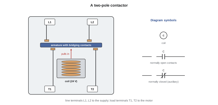
A contactor is a heavy-duty relay designed to switch motor and heating loads. Its contacts are larger, its arc-suppression better and its ratings given for motor loads. HVAC-R equipment uses definite-purpose contactors, built and rated for the duty in refrigeration and air conditioning: a nameplate rating in full-load amperes for motors, a higher locked-rotor ampere rating for the starting current, a resistive ampere rating for heaters, and a coil voltage, commonly 24 volts in residential and light commercial equipment and 24, 120 or 208/240 volts in commercial equipment.
Contactors have one, two or three poles. Three-pole contactors switch three-phase loads; two-pole contactors switch both legs of a 240-volt single-phase load; single-pole contactors switch only one leg, with a bar or shunt connecting the other leg straight through, the arrangement whose shock hazard Lesson 1 described. The supply connects to the line terminals, marked L1, L2 and L3, and the load connects to the load terminals, T1, T2 and T3. Some contactors also have small auxiliary contacts to signal a control board or interlock another device.
Contactor contacts wear. Every time they open under load an arc forms, eroding the contact surfaces. Over thousands of cycles they become pitted and burned, their resistance rises and they heat up. Contacts can also weld closed after a heavy arc, leaving the load running when the thermostat is satisfied. A coil fed with low voltage, as Lesson 6 showed, may not hold the armature firmly, causing chattering, a rapid opening and closing that quickly destroys the contacts and can damage the compressor.
Inspection is visual and electrical. With the power locked out, look for pitting, discolored contacts, melted housings and loose or heat-damaged terminals, and check that the armature moves freely. With the unit running, measure the voltage across each closed pole, from line terminal to load terminal. A good closed contact has almost no resistance, so the reading should be very small, typically a few tenths of a volt or less. A reading of a volt or more means high resistance, heating and a voltage loss at the motor.
# Heat and voltage loss in contactor poles under load: P = V x I
amps = 24.0                                  # compressor running current
poles = {"pole 1": 0.1, "pole 2": 2.6}      # volts measured across each closed pole
for name, vdrop in poles.items():
    r = vdrop / amps
    heat = vdrop * amps
    state = "replace contactor" if vdrop >= 1.0 else "ok"
    print(f"{name}: {vdrop:.1f} V across contacts, {r * 1000:5.1f} milliohms, {heat:5.1f} W of heat  {state}")
supply = 240.0
at_motor = supply - sum(poles.values())
print(f"voltage at the compressor: {at_motor:.1f} V ({at_motor / supply:.1%} of supply)")pole 1: 0.1 V across contacts, 4.2 milliohms, 2.4 W of heat ok pole 2: 2.6 V across contacts, 108.3 milliohms, 62.4 W of heat replace contactor voltage at the compressor: 237.3 V (98.9% of supply)
The second pole adds only about a tenth of an ohm, but at 24 amperes that is more than 60 watts concentrated in a contact the size of a fingernail, enough to keep eroding it and to heat the terminal and wire. The compressor loses more than 2 volts it needed, which matters most when the supply is already low on a hot afternoon. Raj replaced the contactor with one of the same coil voltage and an equal or higher rating, then checked the capacitor and the condenser coil, since both also affect how hard the compressor works.
Overloads and motor protection
Motors need protection against overload, a current somewhat higher than normal for long enough to overheat the windings, caused by high head pressure, low voltage, a failing bearing or a locked rotor. Overload protection responds to heat, either directly or by sensing current over time, so it lets a motor draw its high starting current for a few seconds without tripping.
- Internal overloads, sometimes called line-break overloads, are snap-disc switches inside a hermetic compressor's shell or under its terminal cover that open the motor circuit directly when the windings get too hot or the current too high. Because they sense winding temperature, a compressor that has tripped on its internal overload may take a long time, sometimes an hour or more, to cool enough to reset, which matches the clinic's pattern.
- External overloads are mounted outside the compressor, usually on the terminal block or in the control panel. Pilot-duty overloads open a set of contacts in the control circuit, dropping out the contactor coil.
- Motor starters combine a contactor with an overload relay. The overload relay senses the current in each phase, with bimetal heaters or electronic sensing, and opens a control contact if the current stays too high for too long. Overload relays are set to the motor's nameplate current and have a trip class, such as class 10 or class 20, giving the maximum time in seconds they allow at a high overload.
- Many small fan motors are impedance protected or have an automatic-reset thermal protector inside the winding.
A tripped overload is a symptom, not the problem. When a compressor or motor trips on overload, the technician looks for the cause: voltage at the motor while it runs, current compared with the nameplate, the condition of the capacitor, the condenser coil and fan, the refrigerant charge, and, finally, the motor itself.
Overload protection and short-circuit protection
Fuses and circuit breakers in the panel are a different kind of protection. They protect the conductors and equipment against short circuits and ground faults, very high currents that must be cleared within a fraction of a second. They are sized larger than the motor's running current so that they do not trip during starting. A compressor circuit can therefore have a 30-ampere breaker and a compressor whose running current is 15 amperes: the breaker handles short circuits, and the compressor's own overload handles overloads.
Equipment nameplates give the information to size the circuit: the minimum circuit ampacity, MCA, which sets the conductor size, and the maximum overcurrent protection, MOCP, given as the maximum fuse or HACR breaker size, which must not be exceeded. Those values are calculated by the manufacturer under Article 440 of the NEC, which covers air-conditioning and refrigerating equipment with hermetic motor-compressors. A technician replacing a condensing unit with a different model should compare the new nameplate's MCA and MOCP with the existing circuit, and call in an electrician if the circuit does not match.
Worked problem
Matching a condensing unit to its circuit
A replacement condensing unit's nameplate reads: compressor RLA 14.1 A, LRA 77 A, fan motor FLA 1.2 A, MCA 19 A, MOCP 30 A. The existing circuit is 12 AWG copper on a 25 A breaker. Is the circuit suitable?
Show solution
- \[\text{MCA} \approx 1.25 \times 14.1 + 1.2 = 17.6 + 1.2 \approx 18.8\ \text{A} \to 19\ \text{A}\]
- \[\text{12 AWG copper (typical 75 °C rating)} \approx 20\ \text{A} \ge 19\ \text{A}\]
- \[25\ \text{A breaker} \le 30\ \text{A maximum}\]
Answer: The conductors meet the MCA and the breaker does not exceed the maximum, so the circuit is suitable, provided the conductor's temperature rating and the code's rules for the installation allow it. The calculation shows where the manufacturer's MCA comes from: 125 percent of the largest motor plus the other loads. A technician does not redo the manufacturer's calculation; the point is to check that the field circuit matches the nameplate.
Testing switches, relays and contactors
| Device | Test | Good result | Bad result |
|---|---|---|---|
| Switch or control contacts, power on | Voltage across the contacts with the circuit energized | About 0 V when closed | Full voltage when it should be closed |
| Switch or control contacts, power off | Resistance across isolated contacts | Near 0 Ω closed, OL open | OL when it should be closed, or a few ohms |
| Relay or contactor coil | Voltage at the coil when it should be energized | Correct coil voltage | Missing voltage: look upstream |
| Relay or contactor coil, power off | Coil resistance with one lead lifted | Tens to hundreds of ohms | OL (open) or near 0 Ω (shorted) |
| Contactor poles, running | Voltage from each L to its T terminal | A few tenths of a volt or less | A volt or more: worn contacts |
A coil with the correct voltage across it whose contactor does not pull in has failed, or the armature is mechanically stuck. A contactor that pulls in but whose load does not run, with voltage on the line side and none on the load side, has failed contacts. A load with full voltage at its terminals that does not run is itself faulty. The pattern is always the same: follow the voltage until it disappears.
Common mistakes
MistakeReading a pressure switch drawn open on the diagram as open in the running system.
InsteadDiagrams show contacts at rest; work out each device's state for the condition you are in.
MistakeReplacing a tripped overload without finding why it tripped.
InsteadCheck voltage, current, capacitor, coil, airflow and charge; the overload is a symptom.
MistakeReplacing a contactor with one of a lower rating or a different coil voltage.
InsteadMatch the coil voltage and meet or exceed the FLA, LRA and resistive ratings.
MistakeCondemning a compressor that will not start after an overload trip.
InsteadAllow time for an internal overload to reset, and measure its continuity when cool.
MistakeFiling or sanding pitted contactor contacts.
InsteadReplace the contactor; filed contacts fail quickly.
Summary and key terms
- Switches are described by poles and throws, and contacts by their normal state, NO or NC.
- Pressure and temperature controls are contacts operated by pressure or temperature; their differential sets cut-in and cut-out.
- Relays use a coil to switch another circuit; time-delay relays and anti-short-cycle timers add timing.
- Definite-purpose contactors switch motor and heating loads; check for pitting, chatter and voltage across closed poles.
- Overloads protect motors against excess heat; internal compressor overloads may take an hour or more to reset.
- Breakers and fuses protect against short circuits; MCA sets conductors and the maximum fuse or breaker must not be exceeded.
- Pole
- A separate circuit switched by a switch or relay.
- Throw
- A position that a pole can connect to.
- Normally open
- Contacts that are open when the device is at rest or de-energized.
- Normally closed
- Contacts that are closed when the device is at rest or de-energized.
- Differential
- The difference between a control's cut-in and cut-out settings.
- Relay
- An electrically operated switch with a coil and contacts.
- Contactor
- A heavy-duty relay for switching motor and heating loads.
- Overload
- A device that opens a motor circuit if the motor overheats or draws excess current over time.
- MCA
- Minimum circuit ampacity, the nameplate value used to size conductors.
- Anti-short-cycle timer
- A delay that prevents a compressor from restarting immediately after stopping.
Practice problems
Work each problem on paper first, then reveal the answer to check.
What does SPDT mean?
Show answer
Single-pole, double-throw: one circuit switched between two positions.
A contactor coil has 24 V across it but the contactor does not pull in. What has failed?
Show answer
The coil, or the contactor is mechanically stuck.
You measure 240 V on L1 to L2 and 0 V on T1 to T2 with the contactor pulled in. What is wrong?
Show answer
The contacts are not making; replace the contactor.
Why may a compressor that tripped on overload not restart for an hour?
Show answer
Its internal overload senses winding temperature and must cool before it resets.
Lesson quiz · 5 questions
Score 60% or more to complete this lesson.
Create a free account to save your progress, take quizzes and earn a certificate.