
RAC-130 · Lesson 3 of 12 · 20 min
Series, parallel and control circuits
The brewery's walk-in cooler stopped cooling on a Friday afternoon, the worst possible time for Priya, the head brewer, with a weekend of tap-room sales ahead. The condensing unit outside was silent. Dana opened the control panel, found the wiring diagram inside the door and traced one line with her finger for Theo: thermostat, low-pressure control, high-pressure control, compressor overload, contactor coil. "All of these are in series," she said. "If any one of them opens, the coil drops out and nothing runs. Our job is to find which one is open, and then work out why." Ten minutes later her meter showed 24 volts across the high-pressure control, which meant it was open. The condenser coil behind the unit was plugged with spent-grain dust and lint from the loading dock.
This lesson explains why the meter reading told Dana where to look. It covers the parts of a circuit, series, parallel and combination circuits, the way HVAC-R control circuits use series switches and parallel loads, how voltage readings across switches and loads reveal faults, and voltage drop in conductors.
The parts of a circuit
Every working circuit has the same basic parts. A source supplies the voltage: the utility supply, a transformer secondary or a battery. Conductors carry the current to and from the load. A load converts electrical energy into useful work: a motor, a heater, a coil, a lamp. Controls, such as switches, thermostats, pressure controls and relay contacts, open and close the path to turn loads on and off. Protective devices, such as fuses and breakers, open the circuit if the current becomes dangerously high.
A circuit must be a complete loop for current to flow. An open circuit has a break somewhere, such as an open switch, a broken wire, a burnt contact or a blown fuse; no current flows and the load is off. A short circuit is a path with almost no resistance that bypasses the load, such as two bare wires touching; very large current flows until the protective device opens. A ground fault is a short from a live conductor to grounded metal, such as a compressor winding shorted to its shell.
Series circuits
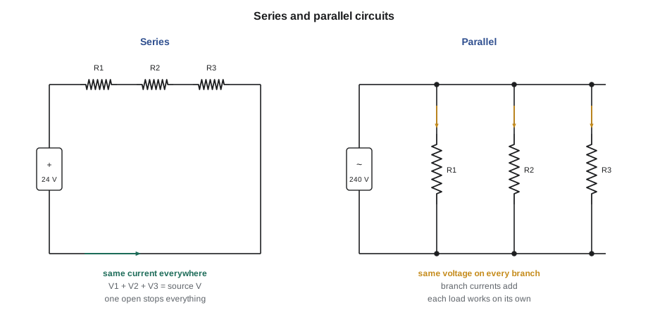
In a series circuit there is only one path for current, so the same current flows through every component. The source voltage is shared among the components in proportion to their resistance, and the voltages across them add up to the source voltage. The total resistance is the sum of the individual resistances.
The important consequence for HVAC-R work is that if any component in a series circuit opens, current stops everywhere. That makes series connection exactly right for switches and safeties, which must all be closed before a load can run, and exactly wrong for loads. Two 120-volt lamps connected in series across 120 volts would share the voltage and glow dimly, and if one burnt out the other would go dark. Loads in HVAC-R equipment are therefore almost never connected in series with each other.
Worked problem
Voltage across components in series
A 24-volt control circuit has a contactor coil of 80 ohms in series with a long thermostat cable whose two conductors add 4 ohms, and a pitted thermostat contact of 1 ohm. Treating the coil as a resistance, find the current and the voltage at the coil.
Show solution
- \[R_T = 80 + 4 + 1 = 85\ \Omega, \qquad I = \frac{24}{85} \approx 0.282\ \text{A}\]
- \[V_{\text{coil}} = 0.282 \times 80 \approx 22.6\ \text{V}, \quad V_{\text{cable}} = 0.282 \times 4 \approx 1.1\ \text{V}, \quad V_{\text{contact}} \approx 0.3\ \text{V}\]
- \[22.6 + 1.1 + 0.3 = 24.0\ \text{V}\]
Answer: The coil gets about 22.6 volts, enough to pull in firmly. The voltages add up to the source voltage, as series circuits always do. If the cable were much longer or the contact much worse, the coil voltage could fall far enough to make the contactor chatter, a problem Lesson 7 returns to.
Parallel circuits
In a parallel circuit each load is connected directly across the source in its own branch, so every branch has the full source voltage. Each branch draws its own current according to its resistance, and the currents add up to the total current drawn from the source. Adding a branch lowers the total resistance and raises the total current.
This is how loads are connected in a building and in a unit. The compressor, the condenser fan motor and the crankcase heater in a condensing unit are each connected across the supply. If the fan motor burns out, the compressor still receives full voltage, although it will soon trip on high pressure without the fan. The total current measured on the supply conductors is the sum of the branch currents, which is how a technician can tell from one clamp reading on the supply whether all the loads are running.
Parallel branches are also why a circuit breaker trips when too many loads are added. Each new branch adds current; the breaker protects the conductors that carry the total.
Combination circuits and HVAC-R control circuits
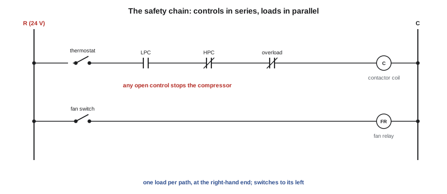
Most real circuits combine series and parallel connections. The standard pattern in HVAC-R controls is a set of switches in series with each load, and the loads, each with their own switches, in parallel across the control transformer. The brewery cooler's control circuit is a typical example:
- The control transformer secondary supplies 24 volts between its R and C terminals.
- From R, current passes through the box thermostat, which closes when the box is warm.
- It then passes through the low-pressure control, which opens if suction pressure falls too low, protecting against a refrigerant leak or a frozen evaporator, and through the high-pressure control, which opens if head pressure rises too high, as it did with the plugged condenser.
- It passes through the overload contact, which opens if the compressor overheats or draws too much current.
- Finally it reaches the contactor coil, which closes the contactor and starts the compressor and condenser fan, and returns to C.
Because the controls are in series, any one of them can stop the compressor. Because the coil is the only load in that path, it receives nearly the full 24 volts when all the controls are closed. A second branch, in parallel, supplies the evaporator fan relay, which has its own controls. A designer can add or remove branches without disturbing the others.
The general rule, which holds for nearly every control circuit in the trade, is that switches go in series with the load they control, and loads go in parallel with each other. Lesson 10 shows how wiring diagrams draw this pattern as a ladder.
Reading voltage across switches and loads
The rules of series circuits give the technician a powerful method. In a series string of controls feeding one load, with the source on:
- A closed switch has almost no resistance, so almost no voltage appears across it: the reading is near zero.
- An open switch stops the current. With no current, there is no voltage drop across the load, so the whole source voltage appears across the open switch.
- The load in a working circuit has nearly the whole source voltage across it. If a load has full voltage across it and still does not work, the load itself is faulty.
That is why Dana's meter read 24 volts across the high-pressure control: it was the open switch in the string. Across the closed thermostat and low-pressure control she read zero; across the coil, also zero, because no current was flowing. Measuring across each component in turn, or measuring from one side of the source to each point along the string, finds the open point quickly. This voltage method, sometimes called hopscotching, is the backbone of the troubleshooting method in Lesson 12.
| Measured across | Reading | Meaning |
|---|---|---|
| A closed switch | About 0 V | Switch is closed and passing current, or no current flows anywhere in the string |
| An open switch | Full source voltage | This switch is the open point |
| The load, circuit working | Nearly full source voltage | Normal |
| The load, load not working | Full source voltage | The load is faulty (open coil, failed motor) |
| The load, load not working | About 0 V | Something upstream is open; look along the controls |
A zero reading across a switch has two possible meanings: the switch is closed, or there is no voltage in that part of the circuit at all, for example because the transformer fuse has blown. Always confirm that the source voltage is present first, by measuring R to C at the transformer, before drawing conclusions from readings along the string.
Calculating series and parallel values
# Series and parallel calculator for resistive branches
def series(*rs):
    return sum(rs)

def parallel(*rs):
    return 1 / sum(1 / r for r in rs)

# Three heater elements of 14.4 ohms each on 240 V
r = 14.4
print("all three in parallel:", round(parallel(r, r, r), 2), "ohms,",
      round(240 / parallel(r, r, r), 1), "A total")
print("one element alone:   ", r, "ohms,", round(240 / r, 1), "A")
print("two in series:        ", series(r, r), "ohms,", round(240 / series(r, r), 1), "A,",
      round((240 / series(r, r))**2 * r), "W per element")

# Control string: coil 80 ohms, cable 4 ohms, contact 1 ohm, source 24 V
parts = {"coil": 80, "cable": 4, "contact": 1}
i = 24 / series(*parts.values())
for name, rr in parts.items():
print(f"voltage across {name:7s}: {i * rr:5.2f} V")all three in parallel: 4.8 ohms, 50.0 A total one element alone: 14.4 ohms, 16.7 A two in series: 28.8 ohms, 8.3 A, 1000 W per element voltage across coil : 22.59 V voltage across cable : 1.13 V voltage across contact: 0.28 V
Wiring two 240-volt heater elements in series would give each only 120 volts and a quarter of its rated heat, which is why heater banks are wired in parallel. The control-string numbers repeat the worked example.
Voltage drop in conductors
Conductors are not perfect. Every wire has a small resistance, which depends on its material, its cross-sectional area and its length. Current through that resistance causes a voltage drop, so the voltage at a load at the end of a long run is lower than at the panel. In a two-wire single-phase circuit the current flows out on one conductor and back on the other, so the drop occurs in both.
where L is the one-way length in feet and r is the resistance of the conductor in ohms per 1,000 feet. Copper 10 AWG has a resistance of about 1.0 ohm per 1,000 feet at normal temperatures, and 12 AWG about 1.6. The National Electrical Code's informational notes recommend sizing conductors so that voltage drop does not exceed about 3 percent in a branch circuit and 5 percent in total; these notes are advice rather than requirements, but equipment manufacturers often require adequate voltage at the unit.
# Voltage drop on a condensing unit circuit (single-phase, copper)
ohms_per_kft = {"14 AWG": 2.5, "12 AWG": 1.6, "10 AWG": 1.0, "8 AWG": 0.63}
amps, volts, length_ft = 22.0, 240.0, 130.0   # one-way length
for size, r in ohms_per_kft.items():
    vd = amps * 2 * length_ft * r / 1000
print(f"{size}: drop {vd:4.1f} V = {vd / volts:5.1%}, voltage at unit {volts - vd:5.1f} V")14 AWG: drop 14.3 V = 6.0%, voltage at unit 225.7 V 12 AWG: drop 9.2 V = 3.8%, voltage at unit 230.8 V 10 AWG: drop 5.7 V = 2.4%, voltage at unit 234.3 V 8 AWG: drop 3.6 V = 1.5%, voltage at unit 236.4 V
Conductor size is chosen first for ampacity, the current the wire can carry without overheating, and then checked for voltage drop on long runs. The calculation also explains why the starting current of a compressor, several times its running current, can dip the voltage enough to make lights flicker or the compressor struggle to start on a long or undersized circuit. Voltage drop also happens in places nobody designed for: a loose lug, a corroded connector or a pitted contactor contact adds resistance in series with the load. Lesson 12 shows how measuring voltage under load finds them.
Common mistakes
MistakeConcluding that a switch is good because it reads 0 V across it, without checking that the circuit has power.
InsteadConfirm the source voltage first; zero across a switch also appears when there is no voltage at all.
MistakeExpecting a load to work when wired in series with another load.
InsteadLoads must be in parallel so each gets full voltage.
MistakeMeasuring current on the supply and assuming every load is running.
InsteadCompare the total with the sum of the expected branch currents, or clamp each branch.
MistakeSizing a long condenser circuit only by breaker size.
InsteadCheck voltage drop, especially for compressor starting.
MistakeTesting a control string with the meter leads across the wrong pair of points.
InsteadMeasure across one component at a time, or from one side of the source to each point in turn.
Summary and key terms
- A circuit needs a source, conductors, a load, controls and protection, in a complete loop.
- Series: same current everywhere, voltages add, resistances add; any open stops everything.
- Parallel: same voltage on every branch, currents add, total resistance falls as branches are added.
- Controls and safeties are in series with the load they control; loads are in parallel with each other.
- With power on, an open switch in a series string shows full source voltage across it; a closed one shows about zero.
- Conductor resistance causes voltage drop; check long runs and poor connections.
- Series circuit
- A circuit with a single path in which the same current flows through every component.
- Parallel circuit
- A circuit in which each load is connected directly across the source in its own branch.
- Combination circuit
- A circuit with both series and parallel parts.
- Safety chain
- The series string of safety controls feeding a contactor coil.
- High-pressure control
- A pressure switch that opens if discharge pressure rises too high.
- Low-pressure control
- A pressure switch that opens if suction pressure falls too low.
- Voltage drop
- The voltage lost across a resistance in a circuit, including conductors and connections.
- Ampacity
- The current a conductor can carry continuously without exceeding its temperature rating.
- Ground fault
- An unintended connection between a live conductor and grounded metal.
Practice problems
Work each problem on paper first, then reveal the answer to check.
Three resistances of 10, 20 and 30 ohms are in series across 120 volts. What is the current?
Show answer
R = 60 Ω, I = 2 A.
The same three resistances are in parallel across 120 volts. What is the total current?
Show answer
12 + 6 + 4 = 22 A.
With the circuit energized and the thermostat calling, you read 24 V across the thermostat contacts. What does this mean?
Show answer
The contacts are not closing; the thermostat is the open point.
Why are safety controls wired in series with the contactor coil?
Show answer
So that any one of them can open the circuit and stop the equipment.
Lesson quiz · 5 questions
Score 60% or more to complete this lesson.
Create a free account to save your progress, take quizzes and earn a certificate.