
RAC-130 · Lesson 12 of 12 · 22 min
Systematic electrical troubleshooting
At the end of Theo's first season, Dana gave him a different kind of test. For a week he would take the first look on every electrical call, with her or Raj beside him saying nothing unless something unsafe was about to happen. "You know the parts," she said. "Now you need a method. A good technician isn't the one who knows the most tricks. It's the one who follows the same steps on every call, so that nothing gets skipped when the customer is watching and the box is warming up." This lesson sets out that method and follows Theo through four of that week's calls, using everything in the course.
A method for every call
Electrical troubleshooting is the process of finding the fault that keeps equipment from following its normal sequence of operation, and then finding its cause. The method below works on almost every call. It is written as steps, but with experience they become one fluent habit.
- Gather information. Ask the customer what happened, when, and whether anything changed: a power failure, a storm, recent work, a new thermostat. Read the work history for the unit.
- Verify the complaint safely. Check that the system really is doing what was reported, and look before touching: burnt smells, melted wiring, tripped breakers, water, ice and missing panels.
- Know the sequence. Read the wiring diagram and the manufacturer's sequence of operation. Decide what should be happening now: which loads should run, which coils should be energized and which contacts closed.
- Check the supply first. Measure voltage at the disconnect and at the unit, and the control voltage at the transformer. A large share of no-run calls end here.
- Follow the voltage. With the system calling, measure along the circuit that should be working until the voltage disappears, or across each device to find the one with full voltage across it. The fault is between the last point with voltage and the first point without.
- Confirm with a second test. Lock out and confirm the suspect component dead: an open switch, an open coil, a failed capacitor, an open winding. Two kinds of evidence are stronger than one.
- Find the root cause. Ask why the part failed. Contacts burn because of low coil voltage or overload; capacitors fail from heat and age; compressors overheat from high head pressure, low voltage or a weak capacitor; fuses blow because of a short.
- Repair, then verify. Fix the cause and the failed part, restore power, and run the system through its full sequence while measuring voltage and current. Compare readings with the nameplate.
- Document and explain. Record the readings, the fault, the cause and the repair on the work order, and explain them to the customer in plain words.
The temptation on every call is to skip straight to the part that usually fails. Sometimes that works; the method exists for the times it does not, and for the safety of the technician, because the steps decide when the equipment is energized and when it is locked out.
Following the voltage
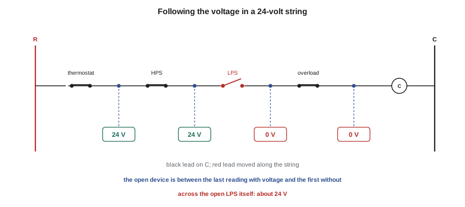
Voltage following is the most important single technique, and it works the same in line-voltage and control circuits. Place one meter lead on the return side of the circuit, such as C for a 24-volt control circuit or L2 for a 240-volt circuit, and move the other lead along the circuit from the source toward the load. Every point before an open device reads full voltage; every point after it reads zero. Alternatively, measure across each device in turn: the open device has full voltage across it, and closed devices read near zero. Lesson 3 explained why.
Voltage following is quick and needs no disconnection of wires, but it is done live. Plan the measurements before opening the panel, use test points on the terminal strip where possible, use the right PPE and a meter of the right category, and keep the other hand clear. Where a reading must be taken on line-voltage terminals close together, clip one lead on with the power off before energizing, so that only one probe has to be placed live.
# Find the open device from voltages measured from C to the load side of each device
def find_open(points, source_v):
    # points: list of (device, volts from C to its load side), in circuit order
    last_ok = "source (R)"
    for device, volts in points:
        if volts < 0.5 * source_v:
            return f"open between {last_ok} and the load side of {device}: {device} is open"
        last_ok = device
    return "voltage reaches the load; if it does not operate, the load itself is faulty"

string = [("thermostat", 24.1), ("high-pressure switch", 24.0), ("low-pressure switch", 0.1),
          ("overload", 0.0), ("contactor coil", 0.0)]
print(find_open(string, 24.1))
print(find_open([(d, 24.0) for d, _ in string], 24.1))open between high-pressure switch and the load side of low-pressure switch: low-pressure switch is open voltage reaches the load; if it does not operate, the load itself is faulty
Call 1: a restaurant walk-in freezer that is warming
The first call was at one of Northfield's two restaurant customers. The walk-in freezer was at 18 °F and rising, the condensing unit on the roof was running, and the evaporator fans inside the box were silent, with ice building on the coil. Theo checked the sequence on the evaporator's diagram: the fans run whenever the box is not in defrost, through a fan delay thermostat that closes once the coil is cold, and a door switch that stops the fans while the door is open.
He measured line voltage at the evaporator's terminal block, 120 volts from hot to neutral, so the supply was good. Following the voltage from neutral along the fan circuit, he found 120 volts on the line side of the door switch and 0 volts on its load side, with the door closed. The door switch was open. With the power locked out, he confirmed it with an ohmmeter: OL with the door closed and the plunger pressed. The switch's plunger was frozen in its housing by ice from a door gasket that no longer sealed. The repair was a new door switch and, more importantly, a new gasket, so the door would seal and stop letting in humid air. He then ran the fans and checked that the coil cleared on its next defrost.
The lesson of the call is in the last step: the switch was the failed part, but the gasket was the cause.
Call 2: the clinic's rooftop unit, no cooling
The clinic's rooftop unit was blowing warm air. At the unit, Theo found the indoor fan running, the condenser fan running and the compressor silent. Its sequence put the compressor and the condenser fan on the same contactor, so a running fan meant the contactor had closed. He measured 208 volts across each pair of the contactor's load terminals, T1 to T2, T2 to T3 and T1 to T3: the compressor was being offered power. The compressor shell was too hot to touch.
That pattern, power at the compressor terminals, a hot shell and no running, pointed to an open internal overload. After locking out and allowing the terminals to be safely reached, he measured the windings of this three-phase compressor and found all three pairs reading OL, while no terminal showed continuity to the shell. On a three-phase compressor whose internal protector sits at the star point of the windings, that pattern means the protector is open. On a single-phase compressor the typical pattern is C–R and C–S both open while S–R reads normal, because the internal overload is in the common lead. In both cases, the overload is open, not necessarily the winding, and a cooled compressor should be retested before anyone condemns it. The next question was why it had opened.
He checked the other loads and found the condenser coil clean and the fan running correctly. He checked the supply: 208, 205 and 203 volts, an unbalance of about 1.3 percent, acceptable. With help from Raj, he attached gauges and found the system's head pressure normal for the outdoor temperature when the compressor last ran, according to the unit's controller history. Then he found it: the contactor's coil voltage was only 18.9 volts with the unit calling, and the contactor chattered under load, its contacts badly pitted. The low coil voltage came from a 40 VA transformer that had been asked to also run an economizer actuator added years earlier. Each chatter had stressed the compressor, which tripped on its overload in the afternoon heat.
Worked problem
Was the transformer overloaded?
The rooftop unit's control loads are: contactor coil 8 VA sealed, economizer actuator 10 VA, thermostat 3 VA, two relays 4 VA each, and the indoor fan control 6 VA. The transformer is rated 40 VA. Find the steady load and the percentage of rating.
Show solution
- \[\text{VA}_{\text{total}} = 8 + 10 + 3 + 2 \times 4 + 6 = 35\ \text{VA}\]
- \[\frac{35}{40} \approx 88\ \% \text{ of rating, before inrush}\]
Answer: The transformer runs at about 88 percent of its rating continuously, and when the contactor pulls in, its inrush pushes the transformer well past its rating, so the voltage sags and the contactor chatters. A 75 VA transformer, a new contactor and a capacitor check, then allowing the compressor to cool and reset, fixed the call. Theo verified 23.6 volts at the coil and compressor current within the nameplate RLA.
Call 3: the residence's make-up air unit
At the seniors' residence, the kitchen make-up air unit's compressor had tripped its overload relay twice in a week. The unit runs on 480-volt three-phase power, so Theo checked his meter's rating, put on the arc-rated PPE the label required, and planned his measurements with Raj before opening the panel. With the unit running, he clamped each compressor lead: two read well above the nameplate RLA and the third read zero. The compressor was single-phasing.
Following the voltage back toward the supply, he measured the line-to-line voltages on the load side of the unit's disconnect: two pairs read only about half the line voltage and one pair read full voltage, the pattern of an open fuse. With the disconnect locked out and the absence of voltage proven, he removed the fuses and found one open. The overload relay had done its job. The cause was also in the disconnect: the fuse clip on that phase was loose and discolored from heat, and the heating had weakened the fuse until it blew. Raj arranged for the residence's electrical contractor to replace the fuse block, and Theo then confirmed balanced current in all three phases and correct rotation before closing up.
Call 4: the arena's snack-bar ice machine
The last call of the week was at the community ice arena, where the snack-bar ice machine tripped its breaker as soon as it was switched on. It is a plug-in, 120-volt machine, a CAT II measurement location. Theo unplugged it, which on a cord-connected appliance is the lockout, and measured the compressor windings at the terminals: C–R, C–S and S–R were all normal and added up correctly. Then he measured from each terminal to the clean copper of the suction line: 0.4 ohms. The winding was shorted to the shell, a ground fault, which explained the instant trip. A megohmmeter test on the compressor alone, with the start relay removed, confirmed it.
A grounded compressor cannot be repaired, and a burnout may leave acid in the system. The arena chose a replacement machine, and Theo recovered the refrigerant from the old one following RAC-120's procedures before it went for recycling. On the work order, he recorded the winding readings and the ground reading, so the decision could be understood by anyone who read it later.
Patterns worth remembering
| Symptom and readings | Likely fault | Look next for |
|---|---|---|
| Control fuse blown; field wire reads near 0 Ω to C or ground | Shorted thermostat or field wire | Chafed cable at cabinet edges, damaged splices |
| Full voltage across one control in a series string | That control is open | Why: high pressure, low pressure, overheating |
| Contactor pulled in, line voltage on T terminals, compressor hot and not running | Open internal overload | Capacitor, voltage, head pressure, coil voltage |
| Compressor hums and trips; capacitor tests low | Failed run capacitor | Heat and age; check the motor current after replacement |
| Two compressor leads high current, third zero | Single-phasing | Fuses, contactor poles, loose connections |
| Terminal to shell reads continuity | Grounded compressor | Megohmmeter confirmation, acid test, replacement |
| Contactor chatters; coil voltage under about 20 V | Weak or overloaded control transformer, wrong tap, long wiring | VA load, tap, splices |
| Voltage across a closed contactor pole above about 1 V under load | Pitted contacts | Replace contactor; check coil voltage |
# Compare running current with nameplate RLA and flag what to check next
def check(name, amps, rla, volts, rated_v):
    ratio = amps / rla
    vdev = (volts - rated_v) / rated_v
    notes = []
    if ratio > 1.0:
        notes.append("above RLA: check head pressure, voltage, capacitor, condenser airflow")
    elif ratio < 0.6:
        notes.append("well below RLA: check charge, valves, compressor pumping")
    if abs(vdev) > 0.10:
        notes.append(f"supply {vdev:+.0%} from rating: outside the usual +/-10 %")
    print(f"{name}: {amps:.1f} A = {ratio:.0%} of RLA at {volts:.0f} V ->", "; ".join(notes) or "normal")

check("clinic RTU compressor after repair", 13.8, 16.0, 205, 208)
check("brewery walk-in compressor",         10.9,  9.6, 231, 230)
check("ductless heat pump at low speed", 2.1, 9.0, 238, 230)clinic RTU compressor after repair: 13.8 A = 86% of RLA at 205 V -> normal brewery walk-in compressor: 10.9 A = 114% of RLA at 231 V -> above RLA: check head pressure, voltage, capacitor, condenser airflow ductless heat pump at low speed: 2.1 A = 23% of RLA at 238 V -> well below RLA: check charge, valves, compressor pumping
Readings are judged against their own context. The ductless heat pump's low current is normal at low compressor speed; the same ratio on a single-speed compressor would point to a refrigerant problem. Numbers become diagnoses only when combined with the sequence, the equipment type and the operating conditions.
Safety on every troubleshooting call
All of the method's live steps are measurements, never repairs. Before each one, decide whether it must be done live; if a dead test will answer the question, use it. Wear the PPE the task and the equipment label require, use a meter rated for the location, keep the customer and bystanders outside the limited approach boundary, and close panels when stepping away. When the measuring is finished, lock out before touching anything, discharge capacitors and wait for drives, and test before touching. The four calls in this lesson ended with satisfied customers because the faults were found and fixed; they ended safely because the method put lockout and testing in the right places.
Common mistakes
MistakeReplacing the part that usually fails without measuring.
InsteadFollow the sequence and the voltage; confirm with a second test.
MistakeStopping when the failed part is found.
InsteadAlways find the cause: why did it fail?
MistakeCondemning a compressor with an open internal overload while it is hot.
InsteadLet it cool and retest; find what made it overheat.
MistakeDoing repairs live because the measurements were live.
InsteadMeasure live only when necessary; lock out for every repair.
MistakeLeaving without verifying operation and recording readings.
InsteadRun the full sequence, compare with the nameplate and document.
Summary and key terms
- Use the same method on every call: information, verify, sequence, supply, follow the voltage, confirm, root cause, repair, verify, document.
- Know what should be happening before measuring; troubleshooting finds where reality differs.
- Following the voltage locates an open device between the last point with voltage and the first without.
- Confirm faults with a second, dead test before replacing parts.
- Failed parts usually have a cause: a gasket, an overloaded transformer, a loose fuse clip, a weak capacitor.
- Measure live only when necessary, with the right PPE and meter; lock out for every repair.
- Troubleshooting
- Finding the fault that stops equipment from following its normal sequence, and its cause.
- Following the voltage
- Measuring from one side of the supply along a circuit to find where voltage disappears.
- Root cause
- The underlying reason a component failed.
- Internal overload
- A protector inside a compressor that opens the motor circuit on high temperature or current.
- Single-phasing
- A three-phase motor running or trying to run with one phase lost.
- Ground fault
- A conductor shorted to grounded metal, such as a winding to a compressor shell.
- Verification
- Running the repaired system through its full sequence while measuring.
- Work order
- The record of the call, readings, fault, cause and repair.
Practice problems
Work each problem on paper first, then reveal the answer to check.
With the black lead on C, you read 24 V at the load side of the thermostat and 0 V at the load side of the high-pressure switch. What is open?
Show answer
The high-pressure switch.
A single-phase compressor reads C–R OL, C–S OL and S–R 3.8 Ω, and the shell is hot. What is the likely fault?
Show answer
An open internal overload; let it cool, retest, and find why it overheated.
Why did the restaurant's door switch fail?
Show answer
Ice from a leaking door gasket froze its plunger; the gasket was the cause.
A three-phase compressor draws 21, 21 and 0 A. What do you check?
Show answer
Fuses, contactor poles and connections for a lost phase.
Lesson quiz · 5 questions
Score 60% or more to complete this lesson.
Create a free account to save your progress, take quizzes and earn a certificate.