
RAC-130 · Lesson 10 of 12 · 20 min
Reading wiring diagrams
Theo's first solo task at the brewery was a small one: Dana asked him to explain to her, using only the wiring diagram glued inside the condensing unit's panel door, what would happen, step by step, when the cooler warmed up and the thermostat called. He studied it for twenty minutes, tracing lines with a pencil, and got the order wrong twice. "Don't worry," Dana said. "Everyone finds their first diagram hard. Once you know the symbols and the way a ladder is read, you will be able to walk into a unit you've never seen and know how it's supposed to work before you touch it. That is most of troubleshooting."
This lesson teaches how to read the diagrams that come with HVAC-R equipment. It covers the types of diagram, the symbols and abbreviations, how ladder diagrams are laid out and read, how a sequence of operation is traced through a diagram, and how diagrams are used to plan measurements.
Types of diagram
Manufacturers supply several kinds of electrical drawing, often printed together on a label inside the unit's access panel:
- A pictorial or component arrangement diagram shows what the parts look like and where they sit in the cabinet. It helps a new technician find the parts.
- A connection or wiring diagram shows every component in roughly its physical position, with each wire drawn from terminal to terminal and marked with its color. It is used to check and replace wiring, because it shows exactly where each wire goes.
- A ladder diagram, also called a schematic, line or elementary diagram, ignores physical layout and shows the circuit as it works electrically. It is the drawing used to understand the sequence of operation and to troubleshoot.
- An installation or field wiring diagram shows the connections the installer makes on site, such as the power supply, the disconnect and the thermostat cable, often with dashed lines for field wiring.
Many units print the connection diagram and the ladder diagram side by side. Experienced technicians usually work from the ladder to understand what should happen, and from the connection diagram to find the actual terminal on which to place a meter lead.
Symbols and abbreviations
Every diagram has a legend explaining its symbols and abbreviations. Symbols are broadly standardized, but they vary between manufacturers and between older and newer drawings, so always read the legend. The table lists symbols and abbreviations common on North American HVAC-R diagrams.
| Item | How it is usually drawn or labeled |
|---|---|
| Conductor | Solid line; heavier lines may show line voltage, lighter ones control wiring |
| Field wiring | Dashed line, often with a note on wire size and type |
| Connected crossing | A dot where lines cross; no dot means the wires cross without connecting |
| Terminal | Small circle or square, labeled with the terminal number or letter |
| Normally open contact | Two short parallel lines with a gap, or a switch blade drawn open |
| Normally closed contact | Two parallel lines with a diagonal line through them, or a blade drawn closed |
| Coil | A circle (or oval) with a letter code such as C, CR, TDR or FR |
| Pressure switch | A contact with a semicircle or flag symbol; labeled HPS, LPS, HPC or LPC |
| Temperature switch | A contact with a zigzag or thermometer symbol; labeled TS, LS (limit) or DTS |
| Motor | A circle labeled COMP, OFM (outdoor fan motor), IFM or EFM (indoor or evaporator fan motor) |
| Capacitor | Two parallel plates, one curved; labeled CAP, RC (run) or SC (start) |
| Transformer | Two coils facing each other, labeled TRANS with primary and secondary voltages |
| Fuse, overload | A small rectangle or S-curve for a fuse; a heater symbol with contacts for an overload |
| Heater | A zigzag resistor symbol; CCH is the crankcase heater, HTR an electric heater |
| Solenoid valve | A coil labeled SOL, LLS (liquid line solenoid) or RV (reversing valve) |
Wire colors are given by abbreviation, such as BK black, WH white, RD red, BL or BU blue, YL yellow, OR orange, BR brown, GR or GN green, and PU purple. A wire marked BK/WH is black with a white stripe. Notes on the diagram give rules the technician must follow, such as using copper conductors only or replacing internal wiring with wire of the same temperature rating, often 105 °C (221 °F).
The letter code on a coil is the key to the drawing. The same code appears beside every contact that coil operates, wherever it is drawn. If a coil is labeled C, the contacts marked C, whether in the compressor's power circuit or in an auxiliary circuit, all change state together when that coil is energized. Some diagrams number the rungs and list, beside each coil, the rung numbers where its contacts appear, with underlined numbers for normally closed contacts.
How a ladder diagram is laid out
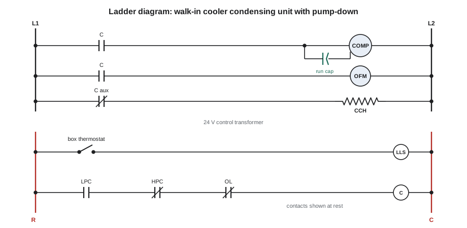
A ladder diagram looks like a ladder on its side or standing up. The two side rails are the two sides of the supply, such as L1 and L2 for line voltage, or R and C for the 24-volt control circuit. Each rung is one path for current between the rails. By convention:
- The supply rails are on the left and right, and the rungs are read from top to bottom, roughly in the order the equipment operates.
- Each rung has one load, or occasionally a few loads in parallel, drawn at the right-hand end, next to the return rail.
- The switches and contacts that control the load are drawn in series to its left, in the order current passes through them.
- Contacts are shown in their normal state, with power off and controls at rest.
- Line-voltage rungs are usually drawn at the top, and the transformer then supplies the control rungs below.
Because of this layout, every rung reads like a sentence: when these switches are closed, this load is energized. The diagram of the brewery's cooler reads, in its control section: when the box thermostat closes, the liquid line solenoid opens. When the low-pressure control, the high-pressure control and the overload are all closed, the contactor coil is energized. In its line section: when the contactor's contacts close, the compressor and the condenser fan run; when the contactor's normally closed auxiliary contact is closed, that is, when the compressor is off, the crankcase heater is on.
Tracing a sequence of operation
The sequence of operation is the order in which things happen when the equipment starts, runs and stops. Reading it from the diagram, with the manufacturer's written sequence where one is supplied, is the most important skill in this lesson. For the brewery cooler with pump-down control, the sequence is:
- Off cycle: the box is cold, so the thermostat is open and the liquid line solenoid is closed. The compressor has pumped the refrigerant into the condenser and receiver, so suction pressure is low and the low-pressure control is open. The contactor is open, the compressor and fan are off, and the crankcase heater is on through the normally closed contact.
- Call: the box warms, and the thermostat closes. The liquid line solenoid opens, letting liquid refrigerant flow to the evaporator.
- Start: suction pressure rises until the low-pressure control closes at its cut-in setting. With the high-pressure control and overload already closed, the contactor coil is energized. The contactor closes, the compressor and condenser fan start, and the crankcase heater switches off.
- Running: the system cools the box. If head pressure rises too high, the high-pressure control opens and stops the compressor; if the compressor overheats, the overload opens.
- Satisfied: the thermostat opens, closing the solenoid. The compressor keeps running and pumps the remaining refrigerant out of the evaporator and suction line until the low-pressure control opens at its cut-out setting, stopping the compressor. The cycle returns to the off state.
Writing the sequence out in this way, before measuring anything, tells the technician what should be true at each step: which coils should be energized and which contacts closed. Troubleshooting is then a matter of finding the first step where reality differs from the diagram. In Theo's exercise, he had first assumed that the thermostat energized the contactor directly, missing the role of the solenoid and the low-pressure control in a pump-down system.
# A tiny ladder-logic evaluator for the cooler's control circuit.
# Each rung: (list of contacts that must be closed, coil or load energized)
def run(state):
    s = dict(state)
    rungs = [
        (["thermostat"],                              "LLS"),       # liquid line solenoid
        (["LPC", "HPC", "overload"],                  "C coil"),    # contactor coil
        (["C contact"],                               "compressor and fan"),
        (["C aux NC"],                                "crankcase heater"),
    ]
    for _ in range(3):                                 # repeat so contacts follow their coils
        s["C contact"] = s.get("C coil", False)
        s["C aux NC"] = not s.get("C coil", False)
        for contacts, load in rungs:
            s[load] = all(s.get(c, False) for c in contacts)
    return {k: s[k] for _, k in rungs}

base = {"thermostat": True, "LPC": True, "HPC": True, "overload": True}
print("normal call:     ", run(base))
print("high head trip:  ", run({**base, "HPC": False}))
print("pumped down: ", run({**base, "thermostat": False, "LPC": False}))normal call: {'LLS': True, 'C coil': True, 'compressor and fan': True, 'crankcase heater': False}
high head trip: {'LLS': True, 'C coil': False, 'compressor and fan': False, 'crankcase heater': True}
pumped down: {'LLS': False, 'C coil': False, 'compressor and fan': False, 'crankcase heater': True}The evaluator follows the ladder rung by rung. With every control closed, the compressor runs and the crankcase heater is off. With the high-pressure control open, the coil drops out, the compressor stops and the heater comes on, which is exactly what Dana found on the Friday call in Lesson 3.
Using the diagram to plan measurements
The ladder tells the technician where to measure. In a series string of controls feeding a coil, measuring from the return rail, C, to each point along the string in turn shows where the voltage disappears: voltage present on the line side of a control but missing on its load side means that control is open. Measuring across each control, as Lesson 3 described, gives the same answer. The connection diagram then shows the actual terminals: for example, that the high-pressure control's two wires land on terminals 4 and 5 of the terminal strip, which is easier and safer to reach than the control itself.
Diagrams also prevent mistakes when replacing parts. Before removing a component, compare the wiring in the unit with the connection diagram, photograph it, and label the wires. Field modifications are common: a previous technician may have added a hard-start kit, bypassed a failed control or changed a fan motor. A unit whose wiring does not match its diagram must be understood before it is worked on, and a bypassed safety control must be restored, never left in place.
Worked problem
Where is the voltage lost?
With the cooler's thermostat calling and the transformer secondary at 25 V, a technician measures from C to each point in the safety string: line side of LPC 25 V, load side of LPC 25 V, load side of HPC 25 V, load side of the overload 0 V, and at the contactor coil 0 V. Which device is open?
Show solution
- \[V_{C \to \text{HPC load}} = 25\ \text{V}, \quad V_{C \to \text{OL load}} = 0\ \text{V}\]
- \[\Rightarrow\ \text{voltage is lost across the overload: } V_{\text{OL}} = 25 - 0 = 25\ \text{V}\]
Answer: The overload contact is open: there is voltage on its line side and none on its load side. The next step is not to replace the overload but to find out why it opened: compressor current, voltage, capacitor and condenser condition.
Common mistakes
MistakeReading a contact's drawn state as its state in the running unit.
InsteadContacts are drawn at rest; work out each one's state at each step of the sequence.
MistakeAssuming the thermostat drives the contactor directly on every system.
InsteadTrace the actual ladder; pump-down, time delays and safeties change the sequence.
MistakeIgnoring the legend because the symbols look familiar.
InsteadSymbols vary between manufacturers; read the legend every time.
MistakeLeaving a bypassed safety control in a unit.
InsteadFind out why it was bypassed, fix the cause, and restore the control.
MistakeReplacing a component without recording the wiring.
InsteadPhotograph and label wires and compare with the connection diagram.
Summary and key terms
- Pictorial diagrams show where parts are; connection diagrams show every wire; ladder diagrams show how the circuit works.
- Read the legend: symbols, abbreviations and wire color codes vary between manufacturers.
- A coil's letter code appears beside every contact it operates; all change state together.
- In a ladder, rails are the supply, each rung is a path, controls are on the left and the load on the right.
- Write out the sequence of operation before measuring; troubleshoot by finding where reality first differs from it.
- Use the ladder to decide where to measure and the connection diagram to find the terminals.
- Ladder diagram
- A schematic drawn as rails and rungs showing how a circuit works electrically.
- Connection diagram
- A diagram showing every wire between terminals in roughly physical layout.
- Rung
- One current path between the rails of a ladder diagram.
- Legend
- The key on a diagram explaining symbols and abbreviations.
- Sequence of operation
- The order in which a system's controls and loads operate.
- Pump-down control
- A control scheme in which the thermostat closes a solenoid and the low-pressure control stops the compressor.
- Liquid line solenoid
- An electrically operated valve that stops liquid refrigerant flow to the evaporator.
- Crankcase heater
- A heater that keeps refrigerant from condensing in the compressor oil during the off cycle.
- Field wiring
- Wiring installed on site, often shown dashed.
Practice problems
Work each problem on paper first, then reveal the answer to check.
On a ladder, where is the load usually drawn on each rung?
Show answer
At the right-hand end, next to the return rail.
A coil is labeled CR. Where are its contacts?
Show answer
Wherever a contact marked CR appears on the diagram.
In a pump-down system, what stops the compressor at the end of a cycle?
Show answer
The low-pressure control, after the solenoid closes and suction pressure falls.
Why is the crankcase heater often fed through a normally closed contactor contact?
Show answer
So it is on only while the compressor is off.
Lesson quiz · 5 questions
Score 60% or more to complete this lesson.
Create a free account to save your progress, take quizzes and earn a certificate.