
PLB-230 · Lesson 9 of 12 · 22 min
Venting categories, vent connectors and common venting
The old atmospheric boiler in the Kingsway mechanical room shared a masonry chimney with a gas water heater that served the caretaker's suite. When the boiler was finally shut down at the end of the job, Dana warned the owner that the water heater, left alone on a chimney sized for both, would become an orphan. "A chimney built for a big boiler is far too large and too cold for one small water heater," she said. "The gases cool, they condense, the draft is weak and the chimney rots from the inside. When you change one appliance on a shared vent, you have to check the whole vent."
This lesson explains how vents work: natural and mechanical draft, the four vent categories, the vent materials used with each, vent connectors and their rules, draft hoods and barometric dampers, and common venting of more than one appliance into one vent. The next lesson covers chimneys and terminations outside the building.
How natural draft works
Hot flue gases are lighter than the cooler air outside. In a vertical vent, the column of hot gas weighs less than an equal column of outdoor air, and the difference in weight creates a small pressure difference, the draft, that pushes the gases up and out. The taller the vent and the hotter the gases compared with the outdoor air, the stronger the draft. The draft is tiny, a few pascals, a few hundredths of an inch of water column, which is why natural-draft venting is so easily upset by wind, a cold vent, a long horizontal run or a depressurized building.
# Theoretical natural draft of a vent (stack effect)
# draft (in. w.c.) = 7.64 * H * (1/To - 1/Ti), temperatures in degrees Rankine
def draft_inwc(height_ft, t_out_f, t_flue_f):
    return 7.64 * height_ft * (1 / (t_out_f + 460) - 1 / (t_flue_f + 460))
for t_out in (0, 32, 70):
    d = draft_inwc(30, t_out, 300)
    print(f"30 ft vent, outdoor {t_out:3d} F, flue 300 F: {d:.3f} in. w.c. ({d * 249.1:5.1f} Pa)")
print(f"cold vent at start-up (flue 100 F, outdoor 70 F): {draft_inwc(30, 70, 100):.3f} in. w.c.")30 ft vent, outdoor 0 F, flue 300 F: 0.197 in. w.c. ( 49.0 Pa) 30 ft vent, outdoor 32 F, flue 300 F: 0.164 in. w.c. ( 40.9 Pa) 30 ft vent, outdoor 70 F, flue 300 F: 0.131 in. w.c. ( 32.6 Pa) cold vent at start-up (flue 100 F, outdoor 70 F): 0.023 in. w.c.
The script shows two lessons. Draft is stronger in cold weather, when the difference between flue and outdoor temperature is largest, and much weaker in mild weather. And a vent that is cold, at the moment the burner first lights, produces very little draft until it warms. That is why an atmospheric appliance can spill briefly at start-up, and why an oversized or exterior masonry chimney, which stays cold, can fail to draw properly at all.
Mechanical draft uses a fan instead. An induced-draft fan on the appliance draws combustion products through the heat exchanger and pushes them into the vent; a forced-draft burner pushes air through the combustion chamber. Mechanical draft lets high-efficiency appliances extract more heat from the flue gases, because the gases no longer need to stay hot to rise. It also means the vent may be under positive pressure, which changes what the vent must be made of.
The four vent categories
Gas appliance vents are grouped by two properties: whether the static pressure in the vent is negative (the gases are drawn out) or positive (they are pushed out), and whether the flue gas temperature is high enough to avoid condensation in the vent or low enough that condensation is likely. The combinations give four categories, and each appliance is certified or listed for one category, with the vent materials named in its instructions.
- Category I: negative pressure, non-condensing. Natural-draft appliances with draft hoods and most fan-assisted, mid-efficiency furnaces and water heaters. Vented with Type B double-wall gas vent, a lined masonry chimney or a listed vent system, and may be common-vented with other Category I appliances under the code's sizing rules.
- Category II: negative pressure, condensing. Rare in practice; few appliances are made for it.
- Category III: positive pressure, non-condensing. Some power-vented appliances. The vent must be gas-tight under pressure, usually a listed stainless steel or special gas vent system, and is never common-vented with other appliances unless the manufacturer specifically allows it.
- Category IV: positive pressure, condensing. High-efficiency condensing appliances such as Kingsway's water heaters. The vent is sealed, made of the listed plastic, polypropylene or stainless material the manufacturer specifies, sloped back toward the appliance so condensate drains to the condensate trap, and normally dedicated to the one appliance.
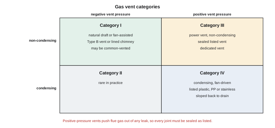
The category decides what can go wrong. A Category I vent leaks inward if it has a gap, so a small leak in a joint draws in room air but does not push out flue gas, provided the draft is working. A Category III or IV vent is under pressure along its length, so any leak pushes flue gas, including carbon monoxide, into the building. Positive-pressure vents must therefore be assembled exactly as listed, with every joint sealed and secured, and the materials named in the instructions, nothing else.
Condensation decides the materials. Flue gases from natural gas contain a lot of water vapor, and when they cool below the dew point in a vent, the condensate is mildly acidic. Category IV materials resist it and slope to drain it. In a Category I vent, condensation must be avoided by keeping the vent warm and the right size; if it happens repeatedly, it corrodes metal vents, deteriorates masonry and drips back into the appliance.
Vent connectors
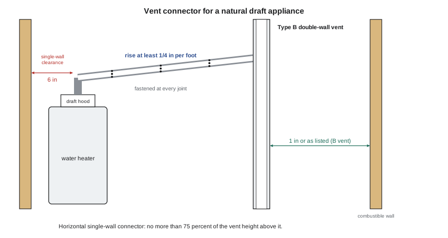
The vent connector is the pipe that joins a Category I appliance's draft hood or flue outlet to the vent or chimney. It may be Type B double-wall vent or, where the code allows, single-wall metal pipe of the required gauge. The connector must be the size of the appliance's flue outlet or larger as the sizing tables require, must rise continuously toward the vent with a minimum upward slope of 1/4 inch per foot, must be as short and direct as possible, and must be fastened securely at every joint, commonly with three screws per joint on single-wall pipe, and supported so that it cannot sag.
Clearance to combustible materials matters because single-wall connectors get hot. The code sets a minimum clearance from single-wall connectors to combustibles, commonly 6 inches for draft-hood appliances, and a smaller clearance for Type B double-wall vent, commonly 1 inch or as listed. The US codes also limit the horizontal length of a single-wall connector to 75 percent of the height of the vent above the connector, and set similar limits for Type B connectors, because a long horizontal connector cools the gases and loses draft. Connectors may not pass through floors, ceilings or fire-rated walls except as the code and the vent listing permit, and single-wall connectors never pass through attics or concealed spaces.
A connector enters a masonry chimney through a thimble or a listed fitting, sealed into the masonry, and does not project into the chimney flue far enough to obstruct it. Where two connectors enter one chimney, they enter at different heights or join with a properly sized manifold, never directly opposite each other.
Draft hoods, barometric dampers and vent dampers
A draft hood, built into or supplied with a natural-draft appliance, separates the burner from the vent. It lets dilution air in, so that the burner's combustion is not affected by changes in the vent draft, and it lets a downdraft or blocked vent spill into the room rather than blowing back into the burner. The draft hood is installed in the position and orientation the manufacturer specifies, never altered, and never connected so that it is sealed.
Spill switches and blocked-vent switches, required on many natural-draft appliances, sense heat at the draft hood when flue gases spill and shut the burner off. They are safety controls. They must never be bypassed, jumped or removed; a spill switch that trips is telling the technician that the venting or air supply has a problem.
A barometric damper is used with some appliances, such as certain conversion burners, to keep the draft steady by admitting room air into the vent when the draft rises. An automatic vent damper closes the vent when the appliance is off to save heat, and must be a listed device, matched to the appliance, interlocked so that the burner cannot fire until the damper is proven open.
Common venting and orphaned appliances
Two or more Category I appliances may share one vent, called common venting, when the code's sizing tables allow it. The smaller appliance's connector normally enters the vent above the larger one's, the connectors join at a properly sized manifold or enter the vent at different heights, and the common vent is sized for the combined input as well as each appliance's minimum input. Category III and IV appliances are not common-vented with others unless the manufacturer lists a common vent system.
When one appliance on a common vent is removed or replaced with a direct-vent model, the remaining appliance may be left on a vent far too large for it. The flue gases have more surface to cool against, the draft is weak, and condensation forms. This is the orphaned water heater problem, and it is one of the most common causes of venting failures in older houses and small buildings. The codes require the remaining vent system to be checked and resized, typically with a liner of the correct size in the chimney, whenever an appliance on a common vent is removed or replaced.
At Kingsway, the caretaker's water heater was left on the old masonry chimney after the boiler was disconnected. Dana's recommendation, accepted by the owner, was to replace it with a direct-vent condensing heater and seal off the old chimney, rather than line the chimney for a small appliance that would soon be replaced anyway.
Worked problem
A spilling draft hood
On a service visit, a natural-draft water heater's spill switch trips every few days. The connector is single-wall pipe, runs 8 feet almost level to a masonry chimney on an exterior wall, and the furnace that once shared the chimney was replaced last year with a condensing model. What is the likely cause, and what should be checked?
Show solution
- Likely cause: an orphaned water heater on an oversized, cold exterior chimney, with a long, nearly level connector, giving weak draft.
- Check the connector slope, length, size and joints against the code and the instructions.
- Inspect the chimney for blockage, deterioration and liner condition.
- Perform a spillage test under worst-case depressurization.
- Do not bypass the spill switch. Remedies include a properly sized liner and a shorter, correctly sloped connector, or replacing the heater with a direct-vent model.
Answer: The spill switch is doing its job; the vent system must be corrected.
Inspecting an existing vent
Every service call on a natural-draft appliance includes a look at the vent. The technician follows the connector from the draft hood to the chimney or vent, checking that every joint is fastened and sealed as required, that the slope is still upward, that the pipe has not rusted through or separated, and that the clearance to combustibles has not been reduced by stored items or new finishes. Rust flakes, white deposits at joints, water stains on the appliance top and soot at the draft hood all point to condensation or spillage.
Where the vent passes out of sight, a mirror, a camera or a chimney inspection by a qualified person checks the rest. Bird nests, fallen liner sections, debris from a deteriorating chimney and blocked caps are common findings, especially on vents that served an appliance removed years ago. The result is recorded on the service report, and an unsafe vent is treated as an unsafe appliance: shut off, tagged and reported in writing.
Common mistakes
MistakeBypassing a spill switch that keeps tripping.
InsteadFind and fix the venting or air supply problem.
MistakeRunning a single-wall connector nearly level for a long distance.
InsteadKeep connectors short with a continuous upward slope.
MistakeCommon-venting a Category IV appliance with a Category I appliance.
InsteadVent Category III and IV appliances separately unless the manufacturer allows otherwise.
MistakeLeaving a water heater orphaned on a large chimney.
InsteadResize or line the vent, or change to a direct-vent appliance.
MistakeUsing ordinary pipe or fittings in a positive-pressure vent.
InsteadUse only the vent materials listed in the appliance instructions.
Summary and key terms
- Natural draft comes from the weight difference between hot flue gas and cooler outdoor air; it is small and easily upset.
- Vent categories I to IV depend on vent pressure and whether the gases condense.
- Category I vents use Type B vent or lined chimneys; Category IV vents are sealed, listed and sloped to drain.
- Connectors rise at least 1/4 inch per foot, are short, fastened and kept at their clearance from combustibles.
- Draft hoods and spill switches are safety devices that must never be altered or bypassed.
- Common venting of Category I appliances follows the code's sizing tables.
- Removing one appliance from a common vent can orphan the other; the vent must be rechecked.
- Draft
- The small pressure difference that moves flue gases up a vent.
- Category I
- A vent category with negative pressure and non-condensing flue gases.
- Category IV
- A vent category with positive pressure and condensing flue gases.
- Type B vent
- Listed double-wall metal gas vent for Category I appliances.
- Vent connector
- The pipe joining an appliance to a vent or chimney.
- Orphaned appliance
- An appliance left alone on a vent sized for more than one appliance.
Practice problems
Work each problem on paper first, then reveal the answer to check.
What two properties define the vent categories?
Show answer
Vent pressure and whether the flue gases condense.
Why must Category IV vents slope back to the appliance?
Show answer
So condensate drains to the condensate trap.
What is the minimum upward slope of a vent connector?
Show answer
1/4 inch per foot.
How long may a single-wall connector run horizontally?
Show answer
No more than 75 percent of the vent height above it.
What is an orphaned water heater?
Show answer
One left alone on a vent sized for more than one appliance.
Why is draft weak in mild weather?
Show answer
The temperature difference between flue gas and outdoor air is smaller.
Lesson quiz · 5 questions
Score 60% or more to complete this lesson.
Create a free account to save your progress, take quizzes and earn a certificate.