
PET-499 · Lesson 9 of 12 · 23 min
Facilities and infrastructure
Hannah's facilities concept is on the critical path, and for good reason: at Spruce Ridge the facilities cost almost as much as the wells, and they decide whether the project can be built and operated safely with sour fluids. Sofia Reyes, who designed Prairie Crest's most recent sour battery, spends two sessions with her. Sofia's view is that the facility design at this stage has three jobs: to define what the battery must do, to size the main equipment well enough to estimate its cost, and to identify the decisions that cannot be changed later without great expense. This lesson follows those three jobs.
What the battery must do
A battery takes the wells' mixed stream of oil, water and gas and separates it into products that can be sold, reused or disposed of. At Spruce Ridge it must also deal with hydrogen sulfide in every stream, supply gas for gas lift, and, in options B and C, inject water. Hannah writes a design basis that states the rates, pressures, compositions and conditions the battery must handle over the life of the field, from the plateau with low water cut to late life with high water cut and gas lift in every well.
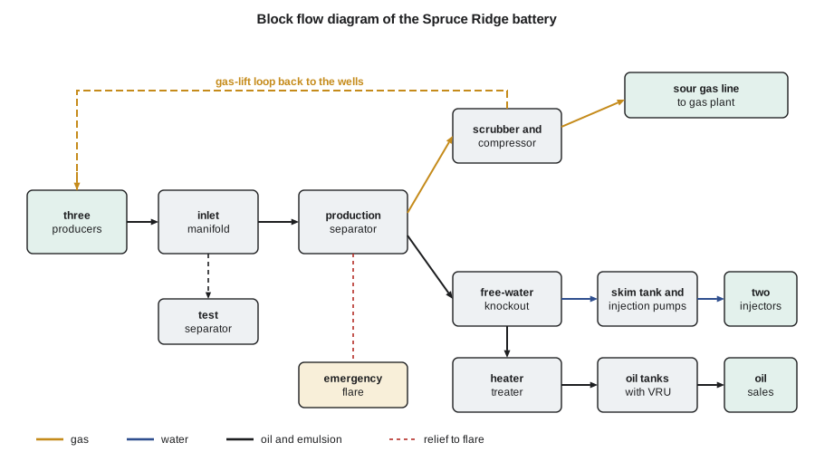
The process is conventional. Production from the wells enters an inlet manifold, where any well can be switched to a test separator to measure its oil, water and gas. The main stream goes to a production separator operating at a moderate pressure, where most of the gas leaves the liquid. The liquids go to a free-water knockout, which removes most of the water, and then a heater treater, which heats the remaining emulsion and separates it to sales specification. The treated oil goes to tanks, from which it is pumped into a pipeline. The water goes through a skim tank to remove residual oil and then to the injection pumps. The gas is scrubbed of liquid droplets and compressed, part of it for gas lift and the rest for the pipeline to the gas plant.
Because every stream is sour, the design has features that a sweet battery might not. All vessels and piping are sour-service materials. The oil tanks are connected to a vapor recovery unit, so that the gas that flashes from the oil in the tanks is compressed and recovered rather than released. H₂S detectors throughout the site are connected to an emergency shutdown system that can isolate the wells and depressurize the plant to the flare. The flare is designed to burn sour gas safely in an emergency, with a continuous pilot. The site is fenced, and its location is chosen with the emergency planning zone in mind, as Lesson 11 discusses.
Separator sizing
Separator size is set either by the gas, which must flow slowly enough that liquid droplets settle out rather than being carried over, or by the liquid, which must stay long enough for gas bubbles to escape and for oil and water to separate. The gas capacity is usually calculated with the Souders-Brown relation, which gives the maximum vapor velocity through the vessel in terms of the liquid and gas densities and an empirical coefficient K that depends on the vessel's internals:
The liquid capacity depends on the retention time, a few minutes for two-phase separation and more for three-phase separation of oil and water. Hannah sizes the production separator for the largest gas flow, which occurs late in life when gas lift is in full use, and for the larger of two liquid cases: the plateau with low water cut, and late life with a water cut near 80 percent. A 20 percent design margin is added to both.
# Facility sizing at Spruce Ridge: separator, water injection and the sour gas line to the gas plant.
import math
SI = False     # True: Canadian case (metric), False: US case (oilfield units)
if SI:
    oil, oil_late, wc_late, gor, lift = 320.0, 130.0, 0.80, 150.0, 50400.0   # plateau and late-life oil m3/d, late water cut, m3/m3, gas-lift gas m3/d
    p_sep, T_sep, Z = 1500.0, 313.15, 0.93                         # separator kPa(a), K
    Bo, Bw, res_p, inj_ii, depth = 1.45, 1.03, 30850.0, 1.2, 3090.0 # injectivity m3/d per kPa; depth m
    L_line, p1, p2, gg, T_line = 22.0, 4500.0, 3500.0, 0.82, 288.0  # km, kPa(a), K
    h2s = 0.022
else:
    oil, oil_late, wc_late, gor, lift = 1600.0, 650.0, 0.80, 900.0, 1.32e6  # bbl/d, scf/STB, scf/d
    p_sep, T_sep, Z = 215.0, 560.0, 0.93                           # psia, deg R
    Bo, Bw, res_p, inj_ii, depth = 1.48, 1.03, 6050.0, 9.0, 13000.0  # injectivity bbl/d per psi; depth ft
    L_line, p1, p2, gg, T_line = 13.0, 650.0, 500.0, 0.80, 520.0    # miles, psia, deg R
    h2s = 0.010
margin = 1.2                                     # design margin on flow rates

# 1. Gas capacity of a vertical separator (Souders-Brown) and liquid retention
if SI:
    gas_std = (oil * gor + lift) * margin        # m3/d at 101.325 kPa, 15 C
    gas_act = gas_std * (101.325 / p_sep) * (T_sep / 288.15) * Z / 86400   # m3/s at separator conditions
    rho_g = p_sep * 28.97 * gg / (Z * 8.314 * T_sep)   # kg/m3
    rho_l, K = 820.0, 0.107                       # m/s, with a mesh pad
    v = K * math.sqrt((rho_l - rho_g) / rho_g)
    d_gas = math.sqrt(4 * gas_act / (math.pi * v))
    liq = max(oil / 0.9, oil_late / (1 - wc_late)) * margin   # larger of plateau (10 percent cut) and late-life liquid, m3/d
    vol = liq / 1440 * 5.0                        # five minutes of retention, m3
    print(f"design gas {gas_std:,.0f} m3/d ({gas_act:.3f} m3/s at {p_sep:,.0f} kPa); gas density {rho_g:.1f} kg/m3; allowable velocity {v:.2f} m/s")
    print(f"minimum diameter for gas {d_gas:.2f} m; liquid design {liq:,.0f} m3/d needs {vol:.1f} m3 of liquid volume (5 min)")
else:
    gas_std = (oil * gor + lift) * margin        # scf/d
    gas_act = gas_std * (14.7 / p_sep) * (T_sep / 520) * Z / 86400          # ft3/s
    rho_g = p_sep * 28.97 * gg / (Z * 10.73 * T_sep)   # lb/ft3
    rho_l, K = 51.2, 0.35                         # ft/s, with a mesh pad
    v = K * math.sqrt((rho_l - rho_g) / rho_g)
    d_gas = math.sqrt(4 * gas_act / (math.pi * v)) * 12
    liq = max(oil / 0.9, oil_late / (1 - wc_late)) * margin
    vol = liq * 5.6146 / 1440 * 5.0               # ft3
    print(f"design gas {gas_std / 1e6:.2f} MMscf/d ({gas_act:.2f} ft3/s at {p_sep:,.0f} psia); gas density {rho_g:.2f} lb/ft3; allowable velocity {v:.2f} ft/s")
    print(f"minimum diameter for gas {d_gas:.0f} in; liquid design {liq:,.0f} bbl/d needs {vol:.0f} ft3 of liquid volume (5 min)")

# 2. Water injection for voidage replacement late in life
water = oil_late * wc_late / (1 - wc_late)
inj = oil_late * Bo + water * Bw                      # reservoir voidage per day, injected as water (Bw)
inj /= Bw
bhp = res_p + inj / 2 / inj_ii                   # two injectors share the water
grad = 10.1 if SI else 0.446                     # injected water gradient, kPa/m or psi/ft
whp = bhp - grad * depth + (1500.0 if SI else 220.0)   # plus tubing friction
pump_kw = inj * (whp * (1 if SI else 6.894757)) / 86400 / 0.70 if SI else inj * 0.158987 * whp * 6.894757 / 86400 / 0.70
print(f"late-life produced water {water:,.0f} {'m3/d' if SI else 'bbl/d'}; injection for full voidage replacement {inj:,.0f} {'m3/d' if SI else 'bbl/d'}")
print(f"bottomhole injection pressure {bhp:,.0f}, wellhead {whp:,.0f} {'kPa' if SI else 'psi'}; pump power at 70 percent efficiency {pump_kw:,.0f} kW")

# 3. Sour gas line to the gas plant: Weymouth equation (oilfield form), smallest standard size that carries the flow
sales = oil * gor * margin * (35.3147 if SI else 1.0)   # scf/d; gas-lift gas is recycled at the battery
P1, P2 = (p1 / 6.894757, p2 / 6.894757) if SI else (p1, p2)
Lmi = L_line / 1.609344 if SI else L_line
Tl = T_line * 1.8 if SI else T_line
for d_in, nps in ((2.067, "2 in"), (3.068, "3 in"), (4.026, "4 in"), (6.065, "6 in")):
    q = 433.5 * (520 / 14.7) * ((P1 ** 2 - P2 ** 2) / (gg * Tl * Lmi * Z)) ** 0.5 * d_in ** 2.667
    if q >= sales: break
print(f"plant gas {sales / 1e6:.2f} MMscf/d" + (f" ({sales / 35.3147:,.0f} m3/d)" if SI else "") + f": {nps} line (inside diameter {d_in} in) carries {q / 1e6:.2f} MMscf/d")
s_t = sales / 35.3147 * h2s / 23.645 * 32.06 / 1000 if SI else sales * h2s / 379.5 * 32.06 / 2204.6
print(f"sulfur in the plant feed: {s_t:.2f} metric tons per day" if SI else f"sulfur in the plant feed: {s_t:.2f} metric tons per day")design gas 3.31 MMscf/d (2.62 ft3/s at 215 psia); gas density 0.89 lb/ft3; allowable velocity 2.63 ft/s minimum diameter for gas 14 in; liquid design 3,900 bbl/d needs 76 ft3 of liquid volume (5 min) late-life produced water 2,600 bbl/d; injection for full voidage replacement 3,534 bbl/d bottomhole injection pressure 6,246, wellhead 668 psi; pump power at 70 percent efficiency 43 kW plant gas 1.73 MMscf/d: 3 in line (inside diameter 3.068 in) carries 1.79 MMscf/d sulfur in the plant feed: 0.66 metric tons per day
The design gas rate is 3.31 MMscf/d, which at 215 psia is 2.62 ft³/s of actual gas. With a mesh-pad coefficient of 0.35 ft/s, the allowable velocity is 2.63 ft/s, and the minimum diameter for gas is 14 inches. The liquid case governs: 3,900 bbl/d of total liquid needs 76 ft³ of liquid volume for five minutes' retention. Hannah selects a horizontal three-phase separator of 60 inches diameter and 16 ft length, which gives that volume with room for the oil and water layers, and notes that the gas capacity has a large margin, useful if the gas-lift demand turns out higher than estimated.
Water injection
In options B and C, the battery must inject enough water to replace the reservoir voidage. Late in life most of that water is produced water, recycled; early in life, when little water is produced, it needs a source of make-up water, which at Spruce Ridge will be a water source well completed in a deeper saline aquifer that is not used for drinking water. Using saline water rather than fresh water for injection is a strong expectation of regulators in both jurisdictions and an obvious point for the community.
Late in life, with 650 bbl/d of oil at an 80 percent water cut, the battery handles 2,600 bbl/d of produced water and must inject 3,534 bbl/d to replace the voidage completely. The reservoir is close to hydrostatic pressure, so the column of water in the injection wells does most of the work: the required bottomhole pressure of 6,246 psi needs a wellhead pressure of only about 670 psi, and the injection pumps need about 43 kW. Injection at Spruce Ridge is cheap to run. The expensive parts are the injection wells, the water source well and the water treatment needed to keep the formation from plugging.
The low wellhead pressure also has a safety advantage: the injection system can be designed to a modest pressure rating, and the injection pressure stays far below the pressure that would fracture the reservoir or its seal. Hannah checks this against the fracture gradient from the discovery well's leak-off test, with a large margin.
Getting the products to market
The oil is light and sweet once the H₂S has been stripped out in the treater, and in the Bakken region it is commonly gathered by crude oil gathering systems owned by midstream companies. Until a gathering connection is built, the oil will be trucked to a terminal about 25 miles away, which at the plateau rate means about ten truckloads a day, with the traffic, road wear, spill risk and emissions that implies. Prairie Crest has a letter of interest from the midstream company that operates the gas gathering in the area to connect Spruce Ridge to its crude and gas systems in return for a fee per barrel and per Mcf. The team assumes the connection in the base case and treats trucking as a temporary measure for the first months.
The sour gas must go to a plant that can sweeten it. The Sheep Creek gas plant, owned by the midstream company, is 13 miles away and has spare capacity for sour inlet gas. The code sizes the line: the plant gas, excluding the gas-lift gas, which circulates at the battery, is 1.73 MMscf/d with the design margin. With the battery compressor delivering 650 psia and an allowed arrival pressure of 500 psia, a 3-inch line just carries 1.79 MMscf/d, and Hannah recommends a 4-inch line for margin and for gas from any future wells. The line will be a regulated gathering line under PHMSA's rules in 49 CFR Part 192 and North Dakota's pipeline requirements, and it will carry about 0.66 metric tons of sulfur a day, which the plant recovers as elemental sulfur.
Worked problem
Sales gas after sweetening
The raw plant gas at plateau is 1.44 MMscf/d with 1.0 percent H₂S and 2.4 percent CO₂. The plant removes both, and recovers natural gas liquids equal to 8 percent of the raw volume as a gas equivalent. Plant fuel and losses take another 4 percent. Roughly how much residue gas is returned to Prairie Crest's account?
Show solution
- Acid gas removed: 1.0 + 2.4 = 3.4 percent.
- Remaining fraction: 1 − 0.034 − 0.08 − 0.04 = 0.846.
- Residue gas ≈ 0.846 × 1.44 ≈ 1.22 MMscf/d.
Answer: About 1.2 MMscf/d of residue gas, plus the liquids. In the economics, Daniel uses a single net value per Mcf of raw gas that combines the residue gas, the liquids and the gathering and processing fees, which is simpler and less error-prone than modeling each stream at this stage.
Cost estimate and its accuracy
Hannah estimates the facility costs by scaling from Prairie Crest's recent sour battery and pipeline projects, adjusted for size with the usual capacity exponent of about 0.6, and adds allowances for items not yet designed. An estimate made this way at the select stage is a class 4 estimate in the classification of AACE International, with an expected accuracy of roughly −15 to −30 percent on the low side and +20 to +50 percent on the high side. That range is large, and it is the reason the economics in Lesson 10 test a 25 percent capital overrun. The define stage will narrow it with a class 3 estimate based on real equipment quotations.
| Item | Option C, phase 1 (million US dollars) | Basis |
|---|---|---|
| Two horizontal producers | 13.6 | Recent Red River and Bakken horizontals, adjusted for depth and sour service |
| Discovery well completion and tie-in | 0.8 | Workover and flowline |
| Battery, injection-ready, with compression and vapor recovery | 9.0 | Scaled from a recent sour battery |
| Flowlines, power and site works | 4.0 | Gas and crude gathering built by the midstream company under a fee |
| Total phase 1 | 27.4 | Class 4 estimate |
| Phase 2 if injection is added: conversion, injector, water plant | 9.0 | Separate estimate |
Decisions that are hard to change later
Sofia's last piece of advice concerns the decisions that lock in the future. The battery site, the pipeline routes and the size of the main lines are expensive to change once built. Building the battery for option C to be ready for injection, with space, foundations and tie-in points for the water plant and pumps, costs about a million dollars more than a battery for depletion only, but it makes adding injection in phase 2 quick and cheap. The same logic applies to the gas line: a 4-inch line costs little more than a 3-inch line, and it leaves room for future wells. These are small insurance premiums that protect the value of the flexibility the team is trying to buy.
Common mistakes
MistakeSizing the separator only for the plateau case.
InsteadCheck the late-life case with high water cut and full gas lift, which often governs.
MistakeSending gas-lift gas to the plant in the sales-line sizing.
InsteadGas-lift gas circulates at the battery; only the produced solution gas goes to the plant.
MistakeUsing fresh water for injection make-up.
InsteadUse saline source water or produced water, as regulators and communities expect.
MistakeTreating a select-stage cost estimate as precise.
InsteadState its class and accuracy range and test the economics against an overrun.
Summary and key terms
- The battery separates the well stream into oil, water and gas, and at Spruce Ridge must handle H₂S in every stream.
- Separator gas capacity follows the Souders-Brown relation; liquid retention often governs the size.
- Water injection late in life is dominated by recycled produced water; near-hydrostatic reservoirs need low injection pressures.
- Oil goes to market by pipeline or gathering system rather than trucks over the field's life; sour gas goes to a sweetening plant.
- Select-stage cost estimates are class 4, with an accuracy of roughly −30 to +50 percent.
- Small investments in flexibility, such as an injection-ready battery and a larger gas line, protect the value of later options.
- Battery
- A field facility that separates, treats, measures and stores produced fluids.
- Free-water knockout
- A vessel that removes free water from the produced liquid.
- Heater treater
- A vessel that heats an oil-water emulsion to separate it to sales specification.
- Vapor recovery unit
- A compressor that captures gas flashing from tanks.
- Souders-Brown coefficient
- An empirical constant relating allowable gas velocity in a separator to the fluid densities.
- Class 4 estimate
- An AACE International cost estimate class typical of the select stage, with a wide accuracy range.
Practice problems
Work each problem on paper first, then reveal the answer to check.
Why does the liquid case usually govern separator size at Spruce Ridge?
Show answer
Late-life liquid rates with high water cut need more retention volume than the gas needs cross-section.
Why is the gas-lift gas excluded from the plant gas line sizing?
Show answer
It is compressed and recycled to the wells at the battery and never leaves the site.
Why is the injection wellhead pressure low at Spruce Ridge?
Show answer
The reservoir is near hydrostatic pressure, so the water column supplies most of the required bottomhole pressure.
What is the purpose of building the phase 1 battery ready for injection?
Show answer
It makes adding injection in phase 2 quick and cheap, protecting the value of the phased option.
Lesson quiz · 5 questions
Score 60% or more to complete this lesson.
Create a free account to save your progress, take quizzes and earn a certificate.