
MEC-460 · Lesson 9 of 12 · 21 min
Inverse kinematics and the Jacobian
Robots are told where to go in the language of the task, not of their joints. The seal-face nest on the assembly fixture is at a position measured in the SCARA's base frame; the arbor on the balancing machine is a pose in R1's user frame. The robot controller must find joint angles that put the tool there. That reverse problem, inverse kinematics, is harder than forward kinematics because it may have several solutions, one, or none, and because near certain configurations small motions of the tool demand enormous joint speeds. This lesson works through inverse kinematics on robot R2, the SCARA that assembles seal faces, where the geometry is simple enough to solve by hand, then introduces the Jacobian, which relates joint speeds to tool speeds and reveals the configurations to avoid.
The SCARA
A SCARA, short for selective compliance assembly robot arm, has two parallel vertical revolute joints that move its arm in a horizontal plane, a vertical prismatic joint for lifting, and a rotation about the vertical at the tool. It is stiff vertically and slightly compliant sideways, which suits pushing parts into holes, and it is fast, often completing a standard pick-and-place cycle well under a second. R2 has an inner link of 325 mm and an outer link of 275 mm, for a reach of 600 mm. Its vertical and tool-rotation joints are independent of the planar ones, so the planar problem is a two-link arm, the classic starting point of inverse kinematics.
Solving the two-link arm
For a planar arm with links \(L_1\) and \(L_2\) and joint angles \(q_1\) and \(q_2\), the tip is at
Squaring and adding eliminates \(q_1\), because the distance from the base to the tip depends only on the elbow angle. By the law of cosines,
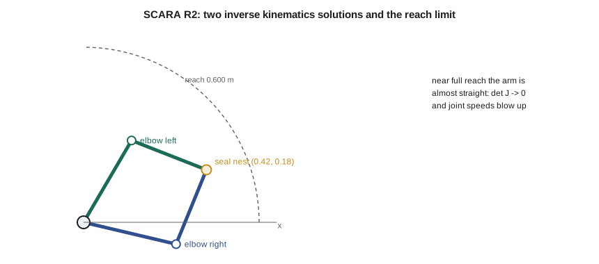
which gives two values of \(q_2\), one positive and one negative, for every reachable point: the elbow-right and elbow-left configurations. If the right-hand side exceeds 1 in magnitude the point is out of reach. With \(q_2\) known, the shoulder angle follows from the direction to the target less the angle the outer link adds: \(q_1 = \operatorname{atan2}(y, x) - \operatorname{atan2}(L_2\sin q_2, L_1 + L_2\cos q_2)\). The two-argument arctangent, atan2, matters: it returns the angle in the correct quadrant, where an ordinary arctangent of y/x would confuse opposite directions.
# Robot R2, a SCARA placing seal faces: inverse kinematics, the Jacobian and singularities
import math
L1, L2 = 0.325, 0.275       # link lengths (m); reach 0.600 m

def ik(x, y, elbow=+1):
    r2 = x * x + y * y
    c2 = (r2 - L1**2 - L2**2) / (2 * L1 * L2)
    if abs(c2) > 1: return None                       # outside the workspace
    q2 = elbow * math.acos(c2)
    q1 = math.atan2(y, x) - math.atan2(L2 * math.sin(q2), L1 + L2 * math.cos(q2))
    return q1, q2
def fk(q1, q2):
    return L1 * math.cos(q1) + L2 * math.cos(q1 + q2), L1 * math.sin(q1) + L2 * math.sin(q1 + q2)
def jac(q1, q2):
    s1, c1, s12, c12 = math.sin(q1), math.cos(q1), math.sin(q1 + q2), math.cos(q1 + q2)
    return [[-L1 * s1 - L2 * s12, -L2 * s12], [L1 * c1 + L2 * c12, L2 * c12]]

target = (0.420, 0.180)      # seal-face nest on the assembly fixture (m, in R2's base frame)
for elbow, name in ((+1, "elbow right"), (-1, "elbow left")):
    q1, q2 = ik(*target, elbow)
    x, y = fk(q1, q2)
    print(f"{name}: q1 {math.degrees(q1):7.2f} deg, q2 {math.degrees(q2):7.2f} deg  (check: x {x:.4f}, y {y:.4f} m)")

# Joint speeds needed to move the seal 0.25 m/s in +x, at the nest and near full reach
for pt in (target, (0.595, 0.0), (0.5999, 0.0)):
    q1, q2 = ik(*pt, +1)
    J = jac(q1, q2)
    det = J[0][0] * J[1][1] - J[0][1] * J[1][0]
    v = (0.25, 0.0)
    qd1 = (J[1][1] * v[0] - J[0][1] * v[1]) / det
    qd2 = (-J[1][0] * v[0] + J[0][0] * v[1]) / det
    print(f"at ({pt[0]:.4f}, {pt[1]:.3f}) m: det J = {det:.5f} m^2 (manipulability {abs(det):.5f}), "
          f"joint speeds {math.degrees(qd1):8.1f} and {math.degrees(qd2):8.1f} deg/s")
print("Target at 0.620 m:", "outside the workspace, no solution" if ik(0.62, 0.0) is None else "reachable")
print(f"Most dexterous elbow angle (largest |det J| = L1 L2 |sin q2|): q2 = 90 deg, |det J| = {L1*L2:.5f} m^2")elbow right: q1 -13.29 deg, q2 81.13 deg (check: x 0.4200, y 0.1800 m) elbow left: q1 59.68 deg, q2 -81.13 deg (check: x 0.4200, y 0.1800 m) at (0.4200, 0.180) m: det J = 0.08831 m^2 (manipulability 0.08831), joint speeds 16.8 and -68.1 deg/s at (0.5950, 0.000) m: det J = 0.02291 m^2 (manipulability 0.02291), joint speeds 170.2 and -371.9 deg/s at (0.5999, 0.000) m: det J = 0.00327 m^2 (manipulability 0.00327), joint speeds 1202.8 and -2624.4 deg/s Target at 0.620 m: outside the workspace, no solution Most dexterous elbow angle (largest |det J| = L1 L2 |sin q2|): q2 = 90 deg, |det J| = 0.08938 m^2
The nest at (0.420, 0.180) m can be reached elbow-right with \(q_1 = -13.29°\) and \(q_2 = 81.13°\), or elbow-left with \(q_1 = 59.68°\) and \(q_2 = -81.13°\). The program checks both by feeding them back through the forward kinematics, a habit worth keeping, since sign errors in inverse kinematics are common and the forward check catches them immediately. Which solution the robot uses is a programming choice. Most SCARA controllers let the programr specify the arm configuration, and moving between configurations requires the arm to pass through the straight-elbow position, which can sweep the outer link through space the programr did not expect. In BC-1, R2 works elbow-left at the nest because the elbow-right solution would bring the inner link close to the test fixture's guard.
Six-axis inverse kinematics
For a six-axis robot like R1, inverse kinematics is more involved, but industrial arms are designed to make it tractable. Their last three joint axes intersect at a single point, the wrist center. Given a tool pose, the wrist center is found by stepping back from the TCP along the tool's z axis by the tool length plus the flange offset. Its position depends only on the first three joints, which can be solved geometrically much like the two-link arm: joint 1 from the direction to the wrist center in plan, and joints 2 and 3 from a triangle in the vertical plane. The last three joints then supply the remaining orientation. Each stage has two solutions, front or back for joint 1, elbow up or down, wrist flipped or not, so a six-axis arm generally has up to eight solutions for one pose. Robot controllers handle the choice through configuration flags stored with each programd position, and a position taught in one configuration and replayed in another can produce an alarming move. Robots without a spherical wrist, such as some collaborative arms, need numerical solutions, iterative methods that start from a guess and refine it.
The Jacobian
Inverse kinematics finds joint positions for one pose. A robot moving along a straight line must also choose joint speeds at every instant, and the relation between joint speeds and tool speeds is the Jacobian matrix. For the planar arm,
Each column is the tool velocity produced by unit speed of one joint. To move the tool at a required velocity, the controller solves this system for the joint speeds, which requires J to be invertible. Its determinant for the two-link arm simplifies to \(L_1 L_2 \sin q_2\), which is zero when the elbow is straight or folded back, \(q_2 = 0\) or 180°. In those configurations the arm cannot move its tip along the line of the arm at all, however fast its joints turn: it has lost a degree of freedom. Such a configuration is a singularity. The magnitude of the determinant, sometimes called the manipulability measure, is largest at \(q_2 = 90°\), where the arm can move equally well in every direction.
The program shows what a singularity means in practice. Moving the seal face at 0.25 m/s in the x direction at the nest needs joint speeds of 16.8 and −68.1 degrees per second, easy for any SCARA. Near full reach at x = 0.595 m, where the arm is almost straight and the x direction points along it, the same tool speed needs 170 and −372 degrees per second. At x = 0.5999 m it needs 1,203 and −2,624 degrees per second, beyond any real motor. A controller following a straight line through such a point either slows the tool dramatically, stops with a fault, or, in older or simpler systems, lets the joints race. Robot programrs therefore keep straight-line moves away from the edge of the workspace, and integrators lay out cells so the working points sit comfortably inside reach. In BC-1, the nest is 457 mm from R2's base, about three quarters of its reach, where the manipulability of 0.0883 m² is close to the maximum of 0.0894 m².
Singularities of six-axis robots
Six-axis arms have three classic singularities, and anyone who programs or checks them should recognize all three. The wrist singularity occurs when axes 4 and 6 line up, which happens when joint 5 passes through zero; the controller cannot tell how to split a rotation between joints 4 and 6, and they may spin rapidly in opposite directions. The shoulder singularity occurs when the wrist center passes through the vertical line of joint 1, so the direction of joint 1 becomes undefined. The elbow singularity occurs at the edge of reach, when the arm is fully stretched. Look again at Lesson 8's working poses: joint 5 is at 60°, well clear of the wrist singularity, which was not an accident of the numbers. Simone's programrs chose the tool orientation to keep it there.
Worked problem
Joint speed for a fast pick
R2 must carry a seal face at 0.8 m/s in the y direction through the point (0.300, 0.300) m, elbow-left. Find the joint speeds.
Show solution
- Inverse kinematics gives \(\cos q_2 = (0.18 - 0.105625 - 0.075625)/(2 × 0.325 × 0.275) = -0.00699\), so \(q_2 = -90.40°\) elbow-left, and \(q_1 = 45° + 40.40° = 85.40°\).
- The Jacobian determinant is \(L_1 L_2 \sin q_2 = -0.0894\) m², near the maximum magnitude, so speeds will be modest.
- Solving \(J\dot q = (0, 0.8)\) gives joint speeds of about 12 and 154 degrees per second.
Answer: About 12°/s at the shoulder and 154°/s at the elbow, comfortably within a SCARA's capability, because the arm is near its best configuration.
What the Jacobian also tells us
The same matrix relates forces as well as speeds. If the tool pushes on its surroundings with a force F, the joint torques needed to hold it are \(\tau = J^T F\). That is how a robot can estimate the force at its tool from its motor currents, and how force limits for collaborative operation are set; Lesson 11 uses it for payload checks. It also governs accuracy: a small joint angle error \(\delta q\) produces a tool error \(J \delta q\), which is the matrix version of the sensitivity calculated in Lesson 8. Near a singularity, where J is nearly singular, the reverse is also true: large tool-space corrections need large joint motions, so a controller using inverse kinematics to correct small errors there becomes unstable. Whether for speed, force or accuracy, the Jacobian is the single most useful object in robot kinematics.
Common mistakes
MistakeUsing arctan(y/x) instead of atan2(y, x).
InsteadUse atan2, which returns the angle in the correct quadrant.
MistakeForgetting that most reachable points have more than one solution.
InsteadSpecify the arm configuration, and check moves between configurations for sweep.
MistakeProgramming straight-line moves through or near a singularity.
InsteadKeep linear moves well inside the workspace and away from wrist alignment.
MistakeNot checking inverse kinematics with the forward model.
InsteadFeed every solution back through forward kinematics.
MistakeAssuming manipulability is the same everywhere in the workspace.
InsteadPlace working points where the Jacobian determinant is large.
Summary and key terms
- Inverse kinematics finds joint angles for a tool pose and may have several solutions or none.
- For a two-link arm, the law of cosines gives the elbow angle and atan2 the shoulder angle; R2 reaches its nest elbow-right or elbow-left.
- Six-axis arms with spherical wrists decouple position and orientation through the wrist center and have up to eight solutions.
- The Jacobian maps joint speeds to tool speeds; for the two-link arm det J = L1 L2 sin q2.
- Near singularities, required joint speeds grow without bound: from 68°/s at the nest to over 2,600°/s at the edge of reach.
- The Jacobian also maps tool forces to joint torques and joint errors to tool errors.
- Inverse kinematics
- Computing joint positions that place the tool at a required pose.
- SCARA
- A robot with two parallel vertical revolute joints, a vertical axis and a tool rotation.
- Configuration
- Which of several inverse kinematics solutions a robot uses, such as elbow left or right.
- atan2
- The two-argument arctangent that returns an angle in the correct quadrant.
- Wrist center
- The point where the last three joint axes of a spherical wrist intersect.
- Jacobian
- The matrix relating joint velocities to tool velocities.
- Singularity
- A configuration where the Jacobian loses rank and the tool cannot move in some direction.
- Manipulability
- A measure, such as the Jacobian determinant, of how freely the tool can move.
- Workspace
- The set of tool positions a robot can reach.
- Numerical inverse kinematics
- An iterative solution that refines a guess using the Jacobian.
Practice problems
Work each problem on paper first, then reveal the answer to check.
A two-link arm with L1 = L2 = 0.4 m must reach (0.5, 0). What is the elbow angle?
Show answer
cos q2 = (0.25 − 0.32)/0.32 = −0.21875, so q2 = ±102.6°.
Can that arm reach (0.85, 0)?
Show answer
No: its reach is 0.8 m, and cos q2 would exceed 1.
Why does R2 lose the ability to move radially when its elbow is straight?
Show answer
det J = L1 L2 sin q2 = 0, so no joint speeds can produce tool motion along the arm.
What happens at a six-axis robot's wrist singularity?
Show answer
Axes 4 and 6 align when joint 5 is at zero, and the controller may command them to spin rapidly in opposite directions.
How does the Jacobian let a robot estimate the force at its tool?
Show answer
Joint torques from motor currents satisfy τ = Jᵀ F, which can be solved for the tool force.
Lesson quiz · 5 questions
Score 60% or more to complete this lesson.
Create a free account to save your progress, take quizzes and earn a certificate.