
MEC-460 · Lesson 1 of 12 · 23 min
Mechatronic systems and the design process
For most of a year Owen Clarke has worked in the test and reliability group at Tidewater Pump Works in Portland. He instrumented the TL-3 test loop, tuned its level and pressure controllers, and wrote finite element models of the heavier-duty TP-80. His new assignment takes him out of the test building and into the impeller shop. Every impeller Tidewater makes, for the TP-80, the VT-12 vertical turbine pump and a long list of service parts, has to be balanced before it is fitted to a shaft. Today that is done by hand. An operator lifts each casting onto the balancing machine, spins it, reads the unbalance, carries it to a drill press, removes metal from the shroud, carries it back and spins it again. Seal faces for the mechanical seal subassemblies are pressed and leak-tested at a bench next door by the same crew.
Denise Cormier, the lead hand in the impeller shop, has been asking for help for two years. The work is repetitive, the castings for the larger impellers are heavy enough to strain backs and wrists over a shift, and when the shop is busy the balancing bench is the bottleneck for the whole assembly line. The plant manager has approved a study for an automated cell, called BC-1, that would take impellers from an infeed conveyor, balance and correct them, assemble and test the seal subassemblies, and pass finished parts to the outfeed. Farah Siddiqui, the senior design engineer, will review and seal the engineering. Gilles Thériault, the controls technologist who programd the TL-3 loop, will own the programmable logic controller. Lucie Arsenault, whose group owns the balancing machine, will define what it needs. An outside integrator, Baywind Automation, will build and install the cell, with Simone Leblanc as their project engineer. Owen's job is to be Tidewater's engineer on the project: to write the requirements, check the integrator's design, and understand every part of it well enough to accept it.
That combination of mechanical hardware, electric actuators, sensors, electronics and software, designed together so that the whole behaves as one machine, is what engineers call a mechatronic system. This course follows the BC-1 project from requirements to the final design review. Each lesson takes one layer of the machine, from motors and drives through microcontrollers, controllers and robot kinematics to safety, and works through the decisions an engineer has to make at that layer, with a runnable Python check of the numbers.
What makes a system mechatronic
A mechatronic system senses something about the physical world, decides what to do with the help of a computer, and acts on the world through actuators. A household example is a washing machine that weighs the load, chooses a water level and spins a motor through a programd profile. An industrial example is a robot that sees where a part is, plans a path and moves its joints along it. The defining feature is not any one technology but the fact that the mechanical design, the electronics and the software are chosen together. A stiffer arm lets the controller use higher gains; a better encoder lets a lighter, cheaper mechanism hit the same accuracy; a few lines of software can remove the need for a mechanical stop.
That coupling is both the opportunity and the risk. A mechanical engineer who sizes a motor without knowing how it will be controlled, or a controls technologist who tunes a loop without knowing the inertia of the axis, can each do their own part competently and still produce a machine that oscillates, overheats or misses its cycle time. Most failures in automation projects happen at the interfaces between disciplines: a sensor whose signal range does not match the input card, a gripper designed for one part tolerance when the castings vary more, a safety function that relies on a brake nobody specified. Owen's main value to the project is that he can follow a requirement across those boundaries.
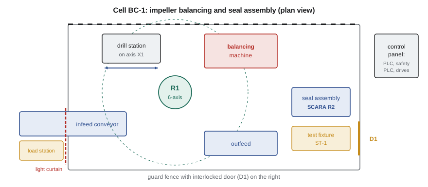
The parts of cell BC-1
The integrator's concept, shown in the figure, has six main subsystems. Robot R1 is a six-axis articulated industrial robot of the 20 kg payload class with a pneumatic gripper. It picks impellers from the infeed conveyor, loads them into the balancing machine, moves them to the drill station for correction and back for a check spin, and places finished parts on the outfeed. The drill station has a spindle on a servo-driven linear axis, X1, which positions the correction holes along the shroud. The balancing machine is the existing hard-bearing machine from Lucie's group, fitted with an automatic door and a communication link so that the controller can start a spin and read the result. Robot R2 is a SCARA, a four-axis robot that is fast and rigid in a horizontal plane, which picks seal faces and places them in an assembly nest. The seal test fixture, ST-1, is a small machine of its own with a microcontroller, a stepper-driven press and a pressure transducer, which seats the faces and checks for leaks. Tying it together is a programmable logic controller, a safety controller, the servo drives and a network that carries signals between them.
Around all of this is the safeguarding: a guard fence, an interlocked door, a light curtain at the operator load station and the safety functions that stop motion when a person could be at risk. Those are not an afterthought added at the end. They shape the layout from the first sketch, because the distance between a light curtain and the hazard behind it depends on how fast the machine can stop, and the stopping time depends on the motors, drives and brakes chosen in the next few lessons. Lesson 12 returns to them in detail.
Requirements first
Every mechatronic project starts with requirements, and the most common cause of an unsatisfactory machine is a requirement that was never written down. Owen begins with a requirements table that has a number, a source and a test for every line. The production requirement comes from the plant's schedule: 300 balancing operations in an eight-hour shift, two shifts a day. Lucie's group supplies the quality requirements: residual unbalance within the ISO 21940-11 grade on the drawing, which for the TP-80 impeller is G6.3, and a record of the initial and final unbalance for every serial number. Denise's crew supplies the practical ones: the operator must be able to load a tray of castings without entering the cell, a jammed part must be clearable in under five minutes, and changing over between impeller models must take less than ten. The health and safety requirements come from OSHA's general industry standards in 29 CFR 1910 and from the robot safety standard ANSI/A3 R15.06-2025, the US adoption of ISO 10218-1 and -2:2025, published in 2025, which Lesson 12 discusses.
Each requirement must be verifiable. A requirement that says the cell shall be fast is useless; one that says the cell shall complete a balancing operation every 86 seconds on average over a shift, demonstrated in an eight-hour run-off at the integrator's shop, can be designed for and tested. Good requirements also say what is not required. The cell does not need to handle the large VT-12 bowls, which stay on the manual bench, and it does not need to work without an operator nearby. Writing that down early keeps the integrator from designing, and charging for, capability nobody asked for.
The V-model
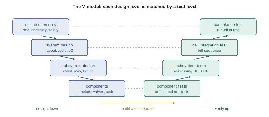
Many automation and automotive organizations organize projects with the V-model shown in the figure. Down the left side, the cell requirements are broken into a system design (layout, cycle, signal list), then subsystem designs (the robot program, the axis, the test fixture), then component choices (motors, valves, sensors, code modules). Up the right side, each level is tested against its own design document: components on the bench, subsystems in isolation, the integrated cell running its full sequence, and finally the acceptance test that proves the original requirements. The value of the V is the pairing. When the integrator writes the subsystem design for axis X1, they must also write how they will test it, and that test traces back to a cell requirement. If a requirement has no test, or a test proves nothing anyone asked for, the gap is visible early.
In practice the stages overlap, and modern teams iterate within the V, simulating the robot cell and testing control code against a virtual machine before any steel is cut. That practice, often called virtual commissioning, catches many logic and reach errors cheaply. It does not replace the physical tests, because simulation models omit exactly the things that tend to go wrong on the shop floor: cable drag, part variation, air pressure sag and the impatience of operators.
Takt time and the cycle budget
The first system-level calculation is whether the cell can keep up. Takt time is the available production time divided by the number of parts required in it. With 50 minutes of each shift lost to breaks, start-up and changeovers, 430 minutes remain, and 300 operations in 430 minutes gives a takt of 86.0 seconds. The cell's cycle time, the time between finished parts at steady state, must be shorter than the takt with some margin for the unexpected.
A naive sequence, in which R1 loads an impeller, waits for the spin, takes it to the drill, waits, brings it back and waits again, adds up to 110.5 seconds and misses the takt by a wide margin. The integrator's sequence keeps two impellers in the cell at once: while one is spinning in the balancing machine, R1 serves the other at the drill station or the conveyors. The cycle time is then set by whichever resource is busiest. The program below adds up the occupation of each resource per impeller. The balancing machine, with two spins, loading and its door, is busy for 79.5 seconds of every cycle; the robot and the drill are much less loaded. The cell can meet takt, but with only 6.5 seconds of margin, and every improvement to cycle time must now come from the balancing machine. That is a useful result early in a project: there is no point paying for a faster robot.
# Cell BC-1 concept check: cycle time against takt, and a placement error budget
import math

demand_per_shift = 300          # impeller balancing operations needed per 8-hour shift
available_min = 8 * 60 - 50     # shift minutes less breaks, start-up and changeover
takt = available_min * 60 / demand_per_shift
print(f"Takt time: {takt:.1f} s per impeller")

# Robot R1 tasks in sequence for one impeller (s); the balancing spin runs while R1 serves the drill
tasks = [("pick from infeed conveyor", 4.0), ("load balancing machine", 5.5),
         ("measure (spin, read unbalance)", 38.0), ("unload to drill station", 6.0),
         ("drill correction holes", 22.0), ("re-check spin", 30.0), ("place on outfeed", 5.0)]
serial = sum(t for _, t in tasks)
print(f"All tasks in series: {serial:.1f} s  ->  {'meets' if serial <= takt else 'misses'} takt")

# With two impellers in the cell, the measuring spins of one overlap the drilling of the other.
# The cycle is then set by the busiest resource.
machine = 38.0 + 30.0 + 5.5 + 2 * 3.0          # balancing machine: two spins, loading, two door cycles
drill = 22.0 + 6.0                              # drill station occupied
robot = 4.0 + 5.5 + 6.0 + 5.0 + 5.5 + 6.0       # R1 handling moves per impeller (two extra moves to re-check)
for name, t in (("balancing machine", machine), ("drill station", drill), ("robot R1", robot)):
    print(f"  {name:18s} busy {t:5.1f} s per impeller")
bottleneck = max(machine, drill, robot)
print(f"Overlapped cycle {bottleneck:.1f} s (bottleneck: balancing machine)  ->  margin {takt - bottleneck:.1f} s")

# Placement error budget for seating the impeller on the balancing arbor (mm, independent sources, RSS)
budget = {"robot repeatability": 0.06, "gripper finger play": 0.10, "impeller bore tolerance": 0.05,
          "conveyor locating pin": 0.15, "arbor position drift with temperature": 0.04}
rss = math.sqrt(sum(v * v for v in budget.values()))
worst = sum(budget.values())
print(f"Placement error: RSS {rss:.3f} mm, worst case {worst:.3f} mm; lead-in chamfer allows 0.50 mm")Takt time: 86.0 s per impeller All tasks in series: 110.5 s -> misses takt balancing machine busy 79.5 s per impeller drill station busy 28.0 s per impeller robot R1 busy 32.0 s per impeller Overlapped cycle 79.5 s (bottleneck: balancing machine) -> margin 6.5 s Placement error: RSS 0.200 mm, worst case 0.400 mm; lead-in chamfer allows 0.50 mm
Error budgets
The second system calculation is accuracy. R1 must seat each impeller's bore over the balancing machine's arbor, which has a lead-in chamfer that will guide a part in if it arrives within 0.50 mm of the arbor's axis. Several independent sources contribute to the placement error: the robot's repeatability, play in the gripper fingers, the tolerance of the cast bore, the locating pin on the conveyor pallet and thermal drift of the arbor's position as the shop warms through the day. The worst case, every error at its limit in the same direction, is their sum, 0.400 mm. If the errors are independent and random, a more realistic estimate combines them as the root of the sum of squares, 0.200 mm. Both fit inside 0.50 mm, so the concept works without a vision system. The table also shows where to spend effort if it did not: the conveyor's locating pin is the largest term, and improving it would help more than buying a more repeatable robot.
Worked problem
Raising the demand
Sales expects demand to rise to 330 operations per shift next year. Does the integrator's overlapped sequence still meet takt?
Show solution
- Takt = 430 × 60 / 330 = 78.2 s.
- The balancing machine is busy 79.5 s per impeller, more than the takt.
- Faster robot moves cannot help; the machine's own occupation must fall, for example by skipping the check spin when the first correction is within a tighter internal limit, or by adding a second machine.
Answer: No. The cell misses a 78.2 s takt by 1.3 s, and only changes at the balancing machine can recover it.
Who decides what
Automation projects involve several parties with different responsibilities. Tidewater, as the owner and employer, is responsible for the safety of its workers and for accepting the cell. Baywind, as the integrator, designs and builds the cell to the owner's specification and, in most contracts, provides the risk assessment and documentation that show the cell complies with the applicable standards. The robot manufacturer supplies a robot that complies with its own part of the robot standard, but a robot alone is not a machine: the safety of the application depends on how it is integrated. Engineering work in the United States that affects public or worker safety is generally carried out under the responsibility of a licensed professional engineer (PE); the regulator here is the Maine State Board of Licensure for Professional Engineers. Farah will review and seal Tidewater's engineering documents, and she expects Owen's requirements and checks to be the kind of record she can sign.
Common mistakes
MistakeStarting with hardware choices before the requirements are written.
InsteadWrite measurable requirements with a source and a test, then choose hardware to meet them.
MistakeAdding cycle times of all tasks in series when the cell can overlap them.
InsteadFind the busiest resource; the cycle time is set by the bottleneck, not the sum.
MistakeAdding every tolerance at its worst to judge accuracy.
InsteadUse the root-sum-square for independent random errors, and the worst case as an upper bound.
MistakeTreating safeguarding as an add-on after the layout is fixed.
InsteadLay out guarding and safety distances from the first concept, since they depend on stopping times.
MistakeLetting each discipline optimize its own part in isolation.
InsteadTrace each requirement across mechanics, electronics and software, where most failures occur.
Summary and key terms
- A mechatronic system combines mechanics, actuators, sensors, electronics and software designed together.
- Cell BC-1 automates impeller balancing and seal assembly with a six-axis robot, a SCARA, a servo axis, a test fixture and a PLC.
- Requirements must be measurable, sourced and testable, and should state what is not required.
- The V-model pairs each level of design with a level of test.
- Takt time is 86.0 s; overlapping two impellers gives a cycle of 79.5 s, set by the balancing machine, with 6.5 s of margin.
- The placement error is 0.200 mm root-sum-square and 0.400 mm worst case, inside the 0.50 mm chamfer.
- Mechatronic system
- A machine in which mechanical design, actuators, sensors, electronics and software are chosen together.
- Takt time
- Available production time divided by the number of parts required in it.
- Cycle time
- The time between finished parts at steady state.
- Bottleneck
- The resource with the longest occupation per part, which sets the cycle time.
- V-model
- A development model pairing each level of design with a matching level of test.
- Virtual commissioning
- Testing control code against a simulated machine before the physical machine exists.
- Error budget
- A list of independent error sources combined to predict total accuracy.
- Root-sum-square
- The square root of the sum of squared errors, used to combine independent random errors.
- Integrator
- The firm that designs, builds and installs an automated cell from components.
- Run-off
- An acceptance test in which a machine runs at rate to prove it meets its requirements.
Practice problems
Work each problem on paper first, then reveal the answer to check.
A shift has 420 minutes available and must produce 280 parts. What is the takt time?
Show answer
420 × 60 / 280 = 90 s.
Three resources are busy 40 s, 72 s and 55 s per part. What sets the cycle time, and what is it?
Show answer
The busiest resource, at 72 s.
Errors of 0.1, 0.2 and 0.2 mm are independent. Give the worst case and root-sum-square totals.
Show answer
Worst case 0.5 mm; RSS √(0.01 + 0.04 + 0.04) = 0.3 mm.
Rewrite the requirement 'the fixture shall be reliable' so it can be tested.
Show answer
For example: 'the fixture shall complete 2,000 consecutive test cycles without an unplanned stop, demonstrated during the run-off.'
Why is the BC-1 placement budget most improved by the conveyor locating pin?
Show answer
It is the largest term, 0.15 mm, and in a root-sum-square the largest term dominates.
Lesson quiz · 5 questions
Score 60% or more to complete this lesson.
Create a free account to save your progress, take quizzes and earn a certificate.