
MEC-460 · Lesson 7 of 12 · 20 min
Programmable logic controllers and industrial networks
The seal test fixture is a microcontroller because it is small and special. The rest of cell BC-1, the conveyors, the clamps, the balancing machine's door, the hand-offs between robots and the operator's screen, is coordinated by a programmable logic controller, or PLC, as almost every industrial machine has been since the late 1960s. Gilles has programd PLCs for twenty years, and his first question to Baywind is which platform they intend to use, because Tidewater's maintenance team must be able to read and change the program after the integrator leaves. This lesson explains what a PLC does, how it is programd, and how it talks to the robots, drives and machines around it.
Why a PLC
PLCs were developed for the automotive industry to replace the cabinets of relays that sequenced production lines, which had to be rewired every model year. A PLC is a rugged industrial computer with input and output modules that connect directly to 24 V sensors, valves and contactors, built to run for decades in electrically noisy, dusty, hot environments. Its operating system is designed for one job: running a control program deterministically and repeatedly. It can be programd and monitored by technicians in graphical languages that look like the relay diagrams they replaced, and its program can be changed while the machine runs. Those features matter more on a shop floor than raw computing power, and they explain why PLCs remain dominant despite cheaper alternatives.
The scan cycle
A PLC runs its program in a repeating scan. First it reads every input and stores the values in an input image table. Then it executes the program from top to bottom using those stored values, writing results into an output image table. Finally it copies the output image to the physical outputs, handles communications and housekeeping, and starts again. A scan typically takes a few to tens of milliseconds. Because the inputs are frozen during the program's execution, the logic sees a consistent snapshot of the machine; because outputs change only at the end, the order of rungs matters in subtle ways that every PLC programr learns, sometimes the hard way. The response time from an input change to an output change can be up to two scans plus the input filter and output switching times, which is fast for a conveyor but far too slow and uncertain for a safety function or a servo loop, which is why those run in dedicated hardware.
Ladder logic
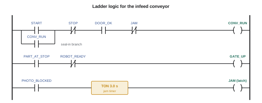
Ladder logic, one of the five languages defined in the IEC 61131-3 standard, draws the program as rungs between two vertical rails, like a relay schematic. A normally open contact passes power when its bit is true; a normally closed contact passes power when its bit is false; a coil sets its bit true when the rung is powered. The first rung in the figure is the classic seal-in or latching circuit: pressing START energizes CONV_RUN, and a contact of CONV_RUN in parallel with START keeps it energized after the button is released, until STOP, the loss of DOOR_OK or a JAM breaks the rung. The second rung raises the pallet stop gate when a part is at the stop and the robot is not ready to pick it. The third rung uses an on-delay timer: if the photo-eye stays blocked for three seconds, the timer's output sets a JAM bit, which stays set until an operator resets it.
IEC 61131-3 also defines function block diagram, structured text, sequential function chart and, in older editions, instruction list, which the 2013 edition deprecated. Structured text, a Pascal-like language, suits calculations and data handling; sequential function chart suits step sequences such as the cell's main cycle. The listing shows the same three rungs in structured text. Real platforms implement the standard with their own extensions, so programs are rarely portable between vendors, but the concepts carry over completely.
(* Infeed conveyor, IEC 61131-3 Structured Text, equivalent to the ladder rungs *)
PROGRAM Infeed
VAR
    JamTimer : TON;
END_VAR

JamTimer(IN := PHOTO_BLOCKED, PT := T#3s);
IF JamTimer.Q THEN JAM := TRUE; END_IF;
IF RESET THEN JAM := FALSE; END_IF;

CONV_RUN := (START OR CONV_RUN) AND NOT STOP AND DOOR_OK AND NOT JAM;
GATE_UP  := PART_AT_STOP AND NOT ROBOT_READY;
END_PROGRAM
The program below imitates a PLC executing these rungs with a 10 ms scan, reading a scripted set of input changes. It shows the conveyor starting when START is pressed, the gate rising while a part waits for the robot, and the jam timer tripping at 9.0 s, three seconds after the photo-eye blocked at 6.0 s, which stops the conveyor until RESET. When the door opens at 12.0 s the conveyor stops. Note what does not happen: after the reset at 10.0 s, the conveyor does not restart by itself; the operator must press START again. Requiring a deliberate start after any stop or reset is a basic rule of machine safety, not a programming nicety.
# A PLC scan cycle in miniature: read inputs, solve rungs, write outputs, for the infeed conveyor
# Rung 1: motor seal-in   CONV_RUN = (START or CONV_RUN) and not STOP and DOOR_OK and not JAM
# Rung 2: stop gate       GATE_UP = PART_AT_STOP and not ROBOT_READY_TO_PICK
# Rung 3: jam timer       TON(PHOTO_BLOCKED, 3.0 s) -> JAM, latched until RESET
inputs_by_time = {0.0: dict(START=0, STOP=0, DOOR_OK=1, PART_AT_STOP=0, ROBOT_READY=0, PHOTO_BLOCKED=0, RESET=0),
                  0.5: dict(START=1), 0.7: dict(START=0), 2.0: dict(PART_AT_STOP=1, PHOTO_BLOCKED=1),
                  3.0: dict(ROBOT_READY=1), 3.4: dict(PART_AT_STOP=0, PHOTO_BLOCKED=0, ROBOT_READY=0),
                  6.0: dict(PHOTO_BLOCKED=1), 9.5: dict(PHOTO_BLOCKED=0), 10.0: dict(RESET=1), 10.1: dict(RESET=0),
                  10.5: dict(START=1), 10.7: dict(START=0), 12.0: dict(DOOR_OK=0)}
scan = 0.010                       # 10 ms scan time
I = {}; out = dict(CONV_RUN=0, GATE_UP=0, JAM=0); timer = 0.0; last = None
t = 0.0
while t <= 12.5 + 1e-9:
    for tt in sorted(inputs_by_time):                 # 1. input image: copy field inputs at the start of the scan
        if tt <= t + 1e-9: I.update(inputs_by_time[tt])
    timer = timer + scan if I["PHOTO_BLOCKED"] else 0.0   # 2. solve rungs top to bottom
    if timer >= 3.0: out["JAM"] = 1
    if I["RESET"]: out["JAM"] = 0
    out["CONV_RUN"] = int((I["START"] or out["CONV_RUN"]) and not I["STOP"] and I["DOOR_OK"] and not out["JAM"])
    out["GATE_UP"] = int(I["PART_AT_STOP"] and not I["ROBOT_READY"])
    state = tuple(out.values())                         # 3. output image written to the field
    if state != last: print(f"  t = {t:5.2f} s  run {out['CONV_RUN']}  gate {out['GATE_UP']}  jam {out['JAM']}"); last = state
    t = round(t + scan, 3)

# EtherNet/IP cyclic I/O load: connections with requested packet intervals (RPI)
conns = [("robot R1", 4, 64), ("robot R2 (SCARA)", 8, 32), ("servo drive X1", 2, 32), ("valve island", 10, 8),
         ("balancing machine gateway", 20, 128), ("safety PLC peer", 10, 16)]
pps = sum(2 * 1000 / rpi for _, rpi, _ in conns)          # one packet each way per RPI
print(f"Cyclic traffic: {pps:.0f} packets per second; a typical adapter is rated for several thousand")
# Modbus TCP: the balancing machine reports unbalance as a 32-bit float in two 16-bit holding registers
import struct
regs = struct.unpack(">HH", struct.pack(">f", 18.37))
print(f"18.37 g mm as two Modbus registers: {regs[0]} and {regs[1]}; word-swapped it would read as "
f"{struct.unpack('>f', struct.pack('>HH', regs[1], regs[0]))[0]:.3e}")t = 0.00 s run 0 gate 0 jam 0 t = 0.50 s run 1 gate 0 jam 0 t = 2.00 s run 1 gate 1 jam 0 t = 3.00 s run 1 gate 0 jam 0 t = 9.00 s run 0 gate 0 jam 1 t = 10.00 s run 0 gate 0 jam 0 t = 10.50 s run 1 gate 0 jam 0 t = 12.00 s run 0 gate 0 jam 0 Cyclic traffic: 2250 packets per second; a typical adapter is rated for several thousand 18.37 g mm as two Modbus registers: 16786 and 62915; word-swapped it would read as -4.950e+32
Signals between PLC and robot
Each robot in the cell has its own controller, which runs the robot's motion program and its own safety functions. The PLC does not move the robot; it coordinates it through a handshake. Owen and Gilles write a signal list, the most important single document for integration, that names every signal, its direction, its meaning and its timing. For the pick at the infeed, the PLC sets PART_AT_STOP when a pallet is on the lifter; the robot, when it is ready, sets ROBOT_READY and moves in; once it has gripped the part and confirmed the gripper sensor, it sets PICK_DONE and leaves; the PLC then lowers the lifter and releases the pallet. Each step waits for the previous one, and each has a timeout leading to a fault message on the operator's screen. A missing or ambiguous signal in the list is a guaranteed delay on site.
Industrial networks
Older machines wired every signal individually. Modern cells connect the PLC to robots, drives, valve islands and remote input blocks over an industrial Ethernet network. Several protocols dominate, and the choice usually follows the PLC platform: EtherNet/IP, which carries the Common Industrial Protocol over standard Ethernet, PROFINET, EtherCAT and Modbus TCP among others. They differ in how they achieve timely delivery. EtherNet/IP and PROFINET exchange cyclic input and output data at a requested packet interval (RPI) or update time chosen per device, typically 1 to 100 ms; EtherCAT passes a frame through every device in turn and achieves cycle times well below a millisecond for coordinated motion. Modbus TCP is a simple request-and-response protocol, slower and less deterministic but supported almost everywhere, which is why the balancing machine's gateway uses it.
The program estimates the cyclic load of the BC-1 network from its connections. Six connections with RPIs from 2 to 20 ms, one packet each way per interval, amount to about 2,250 packets per second. The PLC's network adapter and the switches must handle that with headroom; adapters are rated for several thousand to tens of thousands of packets per second, so this is comfortable, but adding a vision system at 2 ms would change the picture. Managed industrial switches with quality-of-service settings and, for some protocols, multicast filtering keep cyclic traffic from being delayed by bulky traffic such as file transfers.
Modbus holds a lesson of its own. Its data model is 16-bit registers, so a 32-bit floating-point value such as the measured unbalance must be split across two registers, and the standard does not say which half comes first. The program packs 18.37 g·mm into the two registers 16786 and 62915; read in the opposite word order, the same registers decode as about −4.95 × 10³², an absurd number that at least is obvious. A swapped pair that decodes into a plausible but wrong value is worse. The cure is to test every mapped value against a known reading during commissioning, not to trust the documentation.
Worked problem
Response time of the jam detection
The photo-eye has a 2 ms response, the PLC input filter is 3 ms, the scan is 10 ms and the output module switches in 1 ms, then the conveyor's contactor drops out in 20 ms. What is the worst-case time from the photo-eye changing state to the contactor opening, ignoring the three-second jam delay?
Show solution
- Sensor 2 ms + input filter 3 ms.
- Up to two scans, because the input can change just after the input image is read: 20 ms.
- Output 1 ms + contactor 20 ms.
Answer: About 46 ms worst case. That is fine for jam detection but illustrates why safety stops are not built this way.
Security of control systems
Connecting a cell to the plant network brings convenience, such as remote diagnostics and production data, and risk. Industrial protocols were designed for closed networks and many have no authentication: any device that can reach the PLC can often read and write its data. Ransomware attacks on manufacturers and the publicity around attacks on infrastructure have made control system security a normal part of machine specifications. The defensive practices are well established and summarized in the IEC 62443 series of standards: segment the network so the cell sits in its own zone behind a firewall that passes only the traffic it needs; change default passwords and disable unused services; give the integrator remote access only through a controlled, logged and time-limited connection approved by the owner; keep firmware patched on a managed schedule; and back up PLC and robot programs so a damaged program can be restored quickly. Owen writes these into the specification, and Tidewater's IT group, not the integrator, owns the firewall.
Common mistakes
MistakeAllowing a machine to restart by itself after a stop or reset.
InsteadRequire a deliberate start command after any stop, reset or power return.
MistakeUsing the PLC program scan for safety stops or servo loops.
InsteadUse the safety controller and the drives, which have defined and fast response times.
MistakeLeaving signals between PLC and robots undocumented.
InsteadWrite a signal list with direction, meaning, timing and timeout for each signal.
MistakeTrusting the word order of 32-bit Modbus values.
InsteadVerify every mapped value against a known reading during commissioning.
MistakePutting the cell on the plant network with default passwords and open access.
InsteadSegment the network, change defaults and control remote access.
Summary and key terms
- A PLC reads inputs, executes its program and writes outputs in a repeating, deterministic scan.
- Ladder logic shows contacts and coils on rungs; the seal-in rung and timers are its basic idioms.
- IEC 61131-3 defines ladder, function block, structured text and sequential function chart languages.
- Robots and PLCs coordinate through a documented handshake with timeouts.
- The BC-1 network carries about 2,250 packets per second of cyclic data.
- Modbus word order must be verified; cells must be segmented and secured following IEC 62443 practice.
- PLC
- A rugged industrial computer that runs a control program in a repeating scan.
- Scan cycle
- Reading inputs, executing the program and writing outputs, repeated continuously.
- Ladder logic
- A graphical PLC language drawn as contacts and coils on rungs.
- Seal-in circuit
- A rung that keeps an output on after its start input is released.
- On-delay timer
- A timer whose output turns on after its input has been on for a set time.
- IEC 61131-3
- The international standard for PLC programming languages.
- Signal list
- A document defining every signal between devices with its meaning and timing.
- Requested packet interval
- The update period of a cyclic connection on an industrial network.
- Modbus register
- A 16-bit data word in the Modbus data model.
- Network segmentation
- Dividing a network into zones separated by controlled boundaries.
Practice problems
Work each problem on paper first, then reveal the answer to check.
A PLC scan is 15 ms. What is the worst-case delay from an input change to the program acting on it, excluding filters?
Show answer
Up to one scan to be read and one to act: about 30 ms, plus input and output delays.
In the seal-in rung, why must STOP be a normally closed contact in the program?
Show answer
So the rung is broken when STOP is pressed; physically, stop buttons also use normally closed contacts so a broken wire stops the machine.
Four connections run at RPIs of 5, 5, 10 and 20 ms. Estimate the cyclic packet rate.
Show answer
2 × (200 + 200 + 100 + 50) = 1,100 packets per second.
A Modbus value reads as 3.2 × 10³⁵ when 21.6 was expected. What is the likely cause?
Show answer
The two 16-bit registers are being combined in the wrong order.
Name three defensive measures for connecting BC-1 to the plant network.
Show answer
A firewalled zone for the cell, changed default passwords, and controlled, logged remote access, among others.
Lesson quiz · 5 questions
Score 60% or more to complete this lesson.
Create a free account to save your progress, take quizzes and earn a certificate.