
MEC-460 · Lesson 5 of 12 · 22 min
Microcontroller interfacing
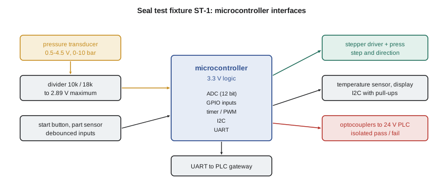
The seal test fixture, ST-1, is the one part of cell BC-1 that Tidewater will design itself. It is small enough that a programmable logic controller would be overkill and specialized enough that nothing off the shelf fits: it must press a seal face into its holder with a stepper-driven press, pressurize the assembly to 4 bar through a solenoid valve, wait for the air to settle, and measure how far the pressure falls in five seconds. A good seal loses a few millibar; a damaged face or a missing O-ring loses tens. Gilles suggests building it around a microcontroller, a single chip that contains a processor, memory and the peripherals needed to talk to the physical world, and reporting pass or fail to the cell PLC. Owen takes on the interface design. If the course on measurements taught him what a transducer's signal means, this lesson is about getting that signal into a computer intact, and getting the computer's decisions back out.
What a microcontroller contains
A typical 32-bit microcontroller for this kind of job runs at tens to a few hundred megahertz from a 3.3 V supply and contains flash memory for its program, a little RAM, and a set of peripherals that do much of the work in hardware. General-purpose input/output (GPIO) pins can be set as digital inputs or outputs. An analog-to-digital converter (ADC) samples voltages on a few pins. Timers count clock pulses to measure intervals, generate periodic interrupts and produce PWM signals. Serial interfaces, typically UART, SPI and I2C, exchange data with other chips and devices. The program configures these peripherals by writing to registers and then mostly reacts to events. Choosing a microcontroller is largely choosing a peripheral set: ST-1 needs at least one ADC channel, a timer able to generate step pulses for the stepper driver, a handful of GPIO, I2C for a temperature sensor and a small display, and a UART for the link to the cell.
Logic levels and protection
A 3.3 V microcontroller reads a pin as low below about 30 percent of its supply and high above about 70 percent, and its pins are damaged by voltages much outside the supply rails. Industrial signals are not like that. PLC inputs and outputs work at 24 V, sensors may output 0 to 10 V or 4 to 20 mA, and long cables pick up noise and the occasional large transient. Every signal that crosses from the field into the microcontroller therefore passes through an interface that converts its level and protects the pin. Common choices are resistor dividers for slow analog voltages, optocouplers for 24 V digital signals, which pass the signal as light across an insulating gap so the two sides share no electrical connection, and dedicated industrial input chips that combine level conversion, filtering and current limiting.
An optocoupler's input is an LED that needs a few milliamperes. Driven from a 24 V PLC output, it needs a series resistor sized for the LED current: \((24 - 1.2)/0.005 = 4{,}560\) Ω, rounded to the standard 4.7 kΩ, which passes 4.9 mA and dissipates 0.11 W. The isolation matters beyond convenience: if a fault puts 24 V or mains voltage onto a field wire, the isolation barrier keeps it out of the microcontroller and its programming port.
The analog-to-digital converter
The ADC compares the pin voltage with a reference and returns an integer. A 12-bit converter divides its reference into \(2^{12} = 4096\) steps, so with a 3.3 V reference one count is 0.806 mV. The quantization error is up to half a count; noise, reference drift and nonlinearity usually exceed it. Most microcontroller ADCs are of the successive approximation type, which sample the voltage onto a small capacitor and then test it bit by bit against an internal DAC. That sampling capacitor must charge through whatever impedance drives the pin in a short sampling time, so a high-impedance source, such as a divider of hundreds of kilohms, gives readings that depend on the previous channel and the sampling time. A modest divider, or a buffer amplifier, avoids the problem.
The transducer chosen for ST-1 outputs 0.5 to 4.5 V over 0 to 10 bar from a 5 V supply. Its maximum output exceeds the ADC's 3.3 V range, so a divider of 10 kΩ and 18 kΩ scales it by 0.643, bringing 4.5 V down to 2.89 V with a little headroom. The program works out the resolution that results: one count is 3.13 mbar of pressure. The pass limit for the leak test is a decay of 8 mbar, so a single count is a large fraction of the quantity being judged, and the fixture must average.
# Seal test fixture ST-1: reading a pressure transducer with a 12-bit ADC, filtering it, and sizing interface parts
import math, random
random.seed(7)

# Transducer: 0 to 10 bar gauge, 0.5 to 4.5 V output on a 5 V supply. ADC: 12 bits, 3.3 V reference.
R1, R2 = 10_000, 18_000                     # divider from transducer output to the ADC pin
k = R2 / (R1 + R2)
v_pin_max = 4.5 * k
print(f"Divider ratio {k:.4f}: 4.5 V becomes {v_pin_max:.3f} V at the pin (reference 3.3 V)")
lsb_V = 3.3 / 4096
bar_per_V = 10.0 / 4.0                      # sensor sensitivity: 10 bar over 4 V of output
lsb_bar = lsb_V / k * bar_per_V
print(f"One ADC count = {1000*lsb_V:.3f} mV at the pin = {1000*lsb_bar:.2f} mbar")

def counts_to_bar(c):
    v_sensor = c * lsb_V / k
    return (v_sensor - 0.5) * bar_per_V

# Simulated readings of a steady 4.000 bar test pressure with 6 mbar RMS electrical noise
true = 4.000
def read():
    v = (0.5 + true / bar_per_V) * k + random.gauss(0, 0.006 / bar_per_V * k)
    return max(0, min(4095, round(v / lsb_V)))
raw = [counts_to_bar(read()) for _ in range(400)]
sd = lambda xs: math.sqrt(sum((x - sum(xs) / len(xs))**2 for x in xs) / (len(xs) - 1))
print(f"Single readings: mean {sum(raw)/len(raw):.4f} bar, scatter {1000*sd(raw):.1f} mbar")
avg16 = [sum(raw[i:i + 16]) / 16 for i in range(0, 400, 16)]
print(f"Averages of 16: scatter {1000*sd(avg16):.2f} mbar (expected {1000*sd(raw)/4:.2f})")
alpha, y, ys = 0.1, raw[0], []               # first-order IIR filter y += alpha (x - y)
for x in raw: y += alpha * (x - y); ys.append(y)
ts = 0.002                                   # 500 samples per second
print(f"IIR filter, alpha {alpha}: scatter {1000*sd(ys[100:]):.2f} mbar, time constant {ts*(1/alpha - 1)*1000:.0f} ms")

# 24 V PLC output into the fixture through an optocoupler: LED needs about 5 mA, drops 1.2 V
R_opto = (24.0 - 1.2) / 0.005
print(f"Optocoupler series resistor {R_opto:.0f} ohm (use 4.7 kohm, {(24-1.2)/4700*1000:.1f} mA, {(24-1.2)**2/4700:.3f} W)")

# I2C pull-ups for the temperature sensor and display: 400 kHz allows a rise time of 300 ns
C_bus = 120e-12
R_max = 300e-9 / (0.8473 * C_bus)
R_min = (3.3 - 0.4) / 0.003
print(f"I2C pull-up between {R_min:.0f} and {R_max:.0f} ohm with {C_bus*1e12:.0f} pF of bus capacitance")

# UART to the cell PLC gateway at 115,200 baud from a 16 MHz clock with 16x oversampling
div = round(16e6 / (16 * 115200))
actual = 16e6 / (16 * div)
print(f"UART divider {div}: actual {actual:.0f} baud, error {100*(actual/115200 - 1):+.2f} %")
for clk in (16e6, 14.7456e6):
    for over in (16, 8):
        d = round(clk / (over * 115200)); e = clk / (over * d) / 115200 - 1
print(f" clock {clk/1e6:.4f} MHz, {over}x oversampling: divider {d:3d}, error {100*e:+.2f} %")Divider ratio 0.6429: 4.5 V becomes 2.893 V at the pin (reference 3.3 V) One ADC count = 0.806 mV at the pin = 3.13 mbar Single readings: mean 4.0001 bar, scatter 6.3 mbar Averages of 16: scatter 1.50 mbar (expected 1.56) IIR filter, alpha 0.1: scatter 1.38 mbar, time constant 18 ms Optocoupler series resistor 4560 ohm (use 4.7 kohm, 4.9 mA, 0.111 W) I2C pull-up between 967 and 2951 ohm with 120 pF of bus capacitance UART divider 9: actual 111111 baud, error -3.55 % clock 16.0000 MHz, 16x oversampling: divider 9, error -3.55 % clock 16.0000 MHz, 8x oversampling: divider 17, error +2.12 % clock 14.7456 MHz, 16x oversampling: divider 8, error +0.00 % clock 14.7456 MHz, 8x oversampling: divider 16, error +0.00 %
Averaging and filtering
The simulated readings scatter by 6.3 mbar about the true 4.000 bar, mostly from electrical noise. Averaging n independent readings divides the scatter by \(\sqrt{n}\), so groups of 16 readings scatter by 1.50 mbar, very close to the expected quarter. A first-order infinite impulse response (IIR) filter, \(y_k = y_{k-1} + \alpha (x_k - y_{k-1})\), does much the same job continuously with one multiplication per sample: with \(\alpha = 0.1\) at 500 samples per second it has a time constant of about 18 ms and reduces the scatter to 1.38 mbar. The price of any filter is lag. Here the pressure is held steady for seconds and the filter's 18 ms delay is irrelevant, but a filter on a fast control signal can destabilize a loop, as Lesson 10 shows.
Filtering only helps random noise. A steady offset, a reference that drifts with temperature or a transducer whose zero shifts are not removed by averaging. ST-1 deals with them by measuring the decay as a difference between two readings taken five seconds apart, so a constant offset cancels, and by logging the reading at atmospheric pressure at each start-up as a check on the zero. The fixture also measures temperature, because a seal assembly warm from handling cools during the test and its trapped air loses pressure even with no leak. Lucie's measurements course would call that a systematic effect that must be corrected, not averaged.
Serial buses
Three serial interfaces appear on almost every microcontroller. A UART sends bytes one bit at a time with start and stop bits and no shared clock; both ends must agree on the baud rate to within a few percent, because the receiver times each bit from the start bit's edge. I2C uses two wires, clock and data, shared by many devices, each with its own address. Its lines are open-drain: devices only pull them low, and resistors pull them high. SPI uses separate data lines in each direction, a clock and a select line for each device, and runs much faster than I2C over short distances on a board.
Each brings its own sizing check. The I2C pull-up resistors must be small enough that the bus capacitance charges within the allowed rise time, 300 ns in fast mode at 400 kHz, and large enough that a device can pull the line low against them with its limited sink current. With 120 pF of bus capacitance the program finds a window between 967 Ω and 2,951 Ω; 2.2 kΩ is a sensible choice. The UART check reveals a trap. Generating 115,200 baud from a 16 MHz clock with 16-times oversampling needs a divider of 8.68, which rounds to 9 and produces 111,111 baud, an error of −3.55 percent, too large for reliable communication when the other end has its own error. Halving the oversampling brings the error to +2.12 percent; a clock of 14.7456 MHz, chosen because it divides exactly into standard baud rates, removes it entirely. Many modern microcontrollers have fractional baud-rate generators that make the problem disappear, which is exactly the kind of detail to confirm in the datasheet before committing to a part.
Worked problem
A 4-20 mA transducer instead
Gilles suggests using a 4-20 mA pressure transmitter, which tolerates long cables and electrical noise better. How would ST-1 read it, and what resolution results with a 150 Ω sense resistor and the same 12-bit, 3.3 V ADC for a 0 to 10 bar range?
Show solution
- The loop current flows through a 150 Ω resistor to ground, giving 0.60 V at 4 mA and 3.00 V at 20 mA, inside the ADC range.
- Span: 2.40 V for 10 bar, so one count of 0.806 mV corresponds to 10 × 0.806/2400 = 3.36 mbar.
- A reading below about 3.6 mA indicates a broken wire or failed transmitter, which a 0.5-4.5 V signal cannot show as clearly.
Answer: Resolution is about 3.4 mbar per count, similar to the voltage transducer, and the live zero gives built-in wire-break detection.
Digital inputs and outputs
Inputs from switches and sensors need more than a level shift. Mechanical contacts bounce, producing a burst of transitions over a few milliseconds when they close, and the next lesson shows how firmware removes the bounce. Inductive sensors and photoelectric sensors in industry come as PNP (sourcing) or NPN (sinking) types, and an input must match. Outputs that drive anything more than an LED, such as the stepper driver's step and direction inputs, a solenoid valve or a relay, need a driver: a transistor or a driver chip that supplies the current, and for coils, a flyback diode or suppressor that absorbs the voltage spike when the coil is switched off. Missing flyback protection is one of the most common causes of microcontrollers that reset mysteriously whenever a valve switches.
Finally, ST-1 must be safe and maintainable. Its press can pinch a finger, so it sits behind a fixed guard with the loading opening sized so a hand cannot reach the press, an approach governed by the reach distances of ISO 13857. The fixture's microcontroller is not used for any safety function; the cell's safety controller, not ST-1's firmware, removes power from the press when the cell's door opens. Safety functions belong in hardware and software designed and verified to the required performance level, which Lesson 12 discusses, and a general-purpose microcontroller program is neither.
Common mistakes
MistakeConnecting a 24 V signal or a 4.5 V sensor directly to a 3.3 V pin.
InsteadUse dividers, optocouplers or industrial input chips that convert level and protect the pin.
MistakeDriving an ADC pin from a very high source impedance.
InsteadKeep the source impedance low or buffer it so the sampling capacitor charges fully.
MistakeExpecting averaging to remove offsets and drift.
InsteadAveraging reduces random noise only; cancel offsets by difference measurements or calibration.
MistakeAssuming any clock gives any baud rate.
InsteadCheck the baud-rate error from the actual divider; keep it to a percent or two.
MistakeSwitching a solenoid coil without suppression.
InsteadFit a flyback diode or suppressor to absorb the turn-off spike.
Summary and key terms
- A microcontroller is chosen mainly for its peripherals: GPIO, ADC, timers and serial interfaces.
- Field signals reach 3.3 V pins through dividers, optocouplers or industrial input devices.
- ST-1's divider scales 4.5 V to 2.89 V; one ADC count is 3.13 mbar, so the fixture averages.
- Averaging 16 readings cut scatter from 6.3 to 1.50 mbar; an IIR filter with α = 0.1 gives 1.38 mbar with an 18 ms time constant.
- I2C pull-ups must fit between sink-current and rise-time limits; UART dividers must keep baud error small.
- Safety functions do not belong in the fixture's general-purpose firmware.
- Microcontroller
- A single chip containing a processor, memory and peripherals for interfacing.
- GPIO
- General-purpose input/output pins configurable by software.
- ADC
- A converter that turns a voltage into an integer count.
- Quantization
- Rounding a continuous value to the nearest digital step.
- Optocoupler
- A device that passes a signal as light across an electrical isolation barrier.
- IIR filter
- A recursive digital filter whose output depends on its previous output.
- UART
- An asynchronous serial interface sending framed bytes without a shared clock.
- I2C
- A two-wire shared serial bus with addressed devices and open-drain lines.
- SPI
- A fast serial bus with separate data lines, a clock and per-device select lines.
- Flyback diode
- A diode across a coil that absorbs the voltage spike when it is switched off.
Practice problems
Work each problem on paper first, then reveal the answer to check.
What is one count of a 10-bit ADC with a 3.3 V reference?
Show answer
3.3/1024 = 3.22 mV.
Readings scatter by 8 mbar. How many must be averaged to bring the scatter to 2 mbar?
Show answer
(8/2)² = 16 readings.
Choose a divider that scales 0 to 10 V into a 3.0 V maximum.
Show answer
The ratio must be 0.30: 23.3 kΩ over 10 kΩ gives exactly 3.0 V, and the standard value 24 kΩ over 10 kΩ gives 2.94 V with a little headroom.
Why does a 4-20 mA signal reveal a broken wire?
Show answer
A healthy loop never falls below 4 mA, so a current near zero means a fault, not a low reading.
A valve coil resets the microcontroller each time it turns off. What is the likely cause and fix?
Show answer
The coil's inductive voltage spike; fit a flyback diode or suppressor across the coil.
Lesson quiz · 5 questions
Score 60% or more to complete this lesson.
Create a free account to save your progress, take quizzes and earn a certificate.