
MEC-460 · Lesson 11 of 12 · 22 min
Robot dynamics, payloads and end effectors
A robot's catalog gives its payload as a single number, 20 kg for R1, and inexperienced users treat it as a simple limit: if the part and gripper weigh less, all is well. They do not. The payload rating assumes the load's center of mass is within a stated distance of the flange and its inertia is within a stated limit, and the robot's speed, accuracy and the life of its gearboxes all depend on how the load is distributed. This lesson looks at what a robot's joints must supply to hold and move a load, how to check a payload against the maker's wrist diagram, and how to design the end effector, the gripper that is usually the only part of a robot cell designed specifically for the job. The robotics program's dynamics course (ROB-300) derives the full equations of motion; here the emphasis is on the checks a mechanical engineer makes when specifying an application.
Static loads: gravity torques
Even standing still, every joint of a robot must hold up the links beyond it and the payload. For a joint, the gravity torque is the sum over everything outboard of mass times g times the horizontal distance from the joint axis to that mass's center. It is largest when the arm is stretched out horizontally, which is why robot makers rate payload at full reach and why the motors of joints 2 and 3, the shoulder and elbow, are the largest in the arm. The program below models R1's shoulder and elbow as a two-link arm in a vertical plane, with illustrative link masses of 18 and 12 kg, and the 10.3 kg payload at the tip.
With the arm horizontal, the shoulder must hold 334.4 N·m and the elbow 147.1 N·m. Raising the shoulder 30° and bending the elbow 45° cuts the shoulder torque to 200.3 N·m and the elbow torque to 38.1 N·m, and with the forearm vertical the elbow carries no gravity torque at all. Robots also counterbalance their heaviest joint with springs or gas struts, so the motor carries less than this simple sum. The lesson for cell layout is that a robot working close in, with its arm folded, uses less of its strength than one reaching to the edge of its envelope, and runs cooler and longer as a result.
Dynamic loads
In motion, each joint must also accelerate the inertia of everything outboard of it, and the links interact. The equations of motion of a serial robot take the general form
where M is a configuration-dependent mass matrix, C collects the Coriolis and centrifugal terms that arise when several joints move at once, and g the gravity torques computed above. The mass matrix changes as the arm folds and unfolds: the inertia the shoulder sees is several times larger with the arm stretched out than folded. Robot controllers evaluate a model of these equations in real time and add the resulting torques as feedforward, the same idea as Lesson 10 applied to a coupled, nonlinear system. That is why robot makers ask for an accurate payload description: if the controller believes the load is lighter than it is, the feedforward is wrong, the feedback must work harder, paths deviate at speed, and the gearboxes and brakes see loads they were not designed for. Many controllers can identify the payload by moving it through a set of test motions; Simone's team will run that identification with each gripper and impeller combination.
The wrist diagram
The most commonly violated limits on an industrial robot are at the wrist. Makers publish an allowable payload diagram showing how far the center of mass may sit from the flange, both along the tool axis and sideways from it, for each payload mass, together with maximum moments about axes 4, 5 and 6 and maximum moments of inertia. A light gripper holding a part far out on a long tool can exceed the wrist's moment limit while weighing far less than the rated payload. The program combines the gripper, 3.1 kg with its center 70 mm from the flange, and the impeller, 7.2 kg at 180 mm and offset 30 mm sideways because the gripper grips the hub off-center. The combined 10.3 kg has its center of mass 147 mm out and 21 mm off-axis.
# Robot R1 carrying an impeller: wrist load check, gripping force, and joint torques of a two-link model
import math
g = 9.81
# Payload: impeller 7.2 kg, gripper 3.1 kg. Centers of mass measured from the flange along the tool axis (z)
#   and sideways from it (offset).
items = [("gripper", 3.1, 0.070, 0.000), ("impeller", 7.2, 0.180, 0.030)]
m = sum(i[1] for i in items)
zc = sum(i[1] * i[2] for i in items) / m
oc = sum(i[1] * i[3] for i in items) / m
L = math.hypot(zc, oc)
M = m * g * L
print(f"Payload {m:.1f} kg, center of mass {1000*zc:.0f} mm out and {1000*oc:.0f} mm off the flange axis ({1000*L:.0f} mm)")
# Illustrative wrist ratings of a 20 kg class robot: axis 4 and 5 moments 49 N m, axis 6 23.5 N m
print(f"Static wrist moment {M:.1f} N m against an axis 5 rating of 49 N m ({100*M/49:.0f} %)")
print(f"Worst-case axis 6 moment, tool axis horizontal: {m*g*oc:.2f} N m against 23.5 N m")
# Moment of inertia about axis 5 (treat each item as a point mass plus a small own inertia)
J5 = sum(mi * (zi**2 + oi**2) for _, mi, zi, oi in items) + 0.5 * 7.2 * 0.105**2 / 2
print(f"Inertia about axis 5: {J5:.3f} kg m^2 (illustrative allowable 1.6 kg m^2)")

# Friction grip with two parallel jaws on the impeller hub: F_grip >= m (g + a) S / (mu n)
mu, n, S = 0.20, 2, 2.0
for a in (0.0, 5.0, 10.0):
    F = 7.2 * (g + a) * S / (mu * n)
    print(f"  vertical acceleration {a:4.1f} m/s^2: squeeze force needed {F:5.0f} N")
# Emergency stop deceleration can reach 15 m/s^2 or more; a form-fit finger avoids depending on friction alone

# Two-link arm in a vertical plane (shoulder and elbow of R1), gravity torques with the payload at the tip
L1, L2 = 0.610, 0.640 + 0.280
m1, m2 = 18.0, 12.0                              # link masses at mid-length (illustrative)
for q2_deg in (0, 45, 90):
    for q1_deg in (0, 30):
        q1, q12 = math.radians(q1_deg), math.radians(q1_deg + q2_deg)
        x1 = 0.5 * L1 * math.cos(q1); x2c = L1 * math.cos(q1) + 0.5 * L2 * math.cos(q12); xt = L1 * math.cos(q1) + L2 * math.cos(q12)
        tau1 = g * (m1 * x1 + m2 * x2c + m * xt)
        tau2 = g * (m2 * 0.5 * L2 * math.cos(q12) + m * L2 * math.cos(q12))
print(f" shoulder {q1_deg:2d} deg, elbow {q2_deg:2d} deg: gravity torque shoulder {tau1:6.1f} N m, elbow {tau2:6.1f} N m")Payload 10.3 kg, center of mass 147 mm out and 21 mm off the flange axis (148 mm) Static wrist moment 15.0 N m against an axis 5 rating of 49 N m (31 %) Worst-case axis 6 moment, tool axis horizontal: 2.12 N m against 23.5 N m Inertia about axis 5: 0.275 kg m^2 (illustrative allowable 1.6 kg m^2) vertical acceleration 0.0 m/s^2: squeeze force needed 353 N vertical acceleration 5.0 m/s^2: squeeze force needed 533 N vertical acceleration 10.0 m/s^2: squeeze force needed 713 N shoulder 0 deg, elbow 0 deg: gravity torque shoulder 334.4 N m, elbow 147.1 N m shoulder 30 deg, elbow 0 deg: gravity torque shoulder 289.6 N m, elbow 127.4 N m shoulder 0 deg, elbow 45 deg: gravity torque shoulder 291.3 N m, elbow 104.0 N m shoulder 30 deg, elbow 45 deg: gravity torque shoulder 200.3 N m, elbow 38.1 N m shoulder 0 deg, elbow 90 deg: gravity torque shoulder 187.3 N m, elbow 0.0 N m shoulder 30 deg, elbow 90 deg: gravity torque shoulder 88.7 N m, elbow -73.6 N m
The static wrist moment is 15.0 N·m, 31 percent of the illustrative 49 N·m rating of axis 5; the worst-case moment about axis 6, which occurs when the tool axis is horizontal so gravity acts across the offset, is 2.12 N·m against 23.5 N·m. The moment of inertia about axis 5 is 0.275 kg·m² against an allowable of about 1.6 kg·m². R1's wrist is comfortably loaded. These ratings are illustrative of the 20 kg class; the real check uses the selected robot's own diagram, and Owen asks Baywind to include it, marked with the payload point, in the design report.
End effectors
The end effector is where the robot meets the part, and it is where most of a cell's engineering effort and early trouble concentrates. Grippers come in a few families. Mechanical grippers close two or three jaws, driven pneumatically or electrically, and hold parts either by friction, squeezing hard enough that friction resists the load, or by form, with fingers shaped to cradle the part so that it cannot fall out even without squeeze force. Vacuum grippers use suction cups and suit flat, smooth parts such as R2's seal faces. Magnetic grippers hold steel. Specialized tools include needle grippers for textiles and soft grippers for food. The gripper's fingers are usually custom-machined for the part, and good practice makes them quick to change, with a tool changer if one robot must use several grippers.
Sizing a friction grip
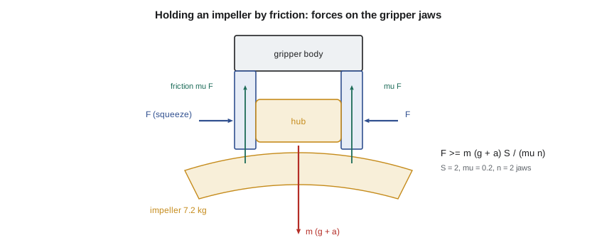
For a friction grip with n jaws, each pressing with force F, and a coefficient of friction μ between the jaws and the part, the total friction available is \(\mu n F\). It must exceed the weight plus the inertial force of the largest acceleration, times a safety factor S:
With the 7.2 kg impeller, steel fingers with polyurethane pads giving μ = 0.2, two jaws and a factor of 2, the squeeze force must be 353 N when stationary, 533 N for 5 m/s² of upward acceleration and 713 N for 10 m/s². Robots can decelerate much faster than they accelerate in normal motion when an emergency stop applies the brakes, and decelerations of 15 m/s² or more are possible. A friction grip sized for normal motion can release a part in an emergency stop, which would turn a stopped robot into a dropped casting. The common solutions are to shape the fingers so the impeller's shroud rests on them, a form-fit grip that holds the part even with no squeeze, and to use a gripper with a spring or a check valve that keeps its jaws closed if air pressure is lost. Baywind's design does both, and Owen adds a requirement that the gripper be tested by cutting its air supply while holding an impeller.
Worked problem
Choosing the gripper
Baywind proposes a pneumatic parallel gripper rated at 1,100 N of total grip force at 6 bar, with jaw pads giving μ = 0.2. R1's normal moves have peak vertical accelerations of 6 m/s². Check the friction grip with a safety factor of 2, and state what the form-fit fingers add.
Show solution
- Required: \(7.2 × (9.81 + 6) × 2/(0.2 × 2) = 569\) N per jaw, about 1,140 N in total if each jaw must supply 569 N.
- Rated 1,100 N total is 550 N per jaw, about 3 % short of the friction requirement with S = 2.
- With the shroud resting on the shaped fingers, the vertical load is carried by contact, not friction; the squeeze only needs to stop the part rotating or sliding sideways.
Answer: On friction alone the gripper is marginal, but with form-fit fingers it is adequate, because the grip no longer depends on friction for the vertical load.
Gripper sensing and compliance
A gripper should tell the controller what happened. Sensors on the jaws confirm open, closed with a part, and closed without one, the last indicating a missed pick, so the robot does not carry an empty gripper to the balancing machine and wait for a spin that never starts. For insertion tasks such as seating an impeller bore over the arbor, a small amount of compliance helps more than precision: a compliance device, a spring-loaded mount between the flange and the gripper, lets the part shift and tilt slightly to follow the arbor's chamfer, absorbing the 0.2 mm placement error estimated in Lesson 1. Force-torque sensors at the wrist go further, measuring the contact forces so the robot can search for a hole or detect a jam, and they are standard on many collaborative robots.
Gearboxes and life
Industrial robot joints use compact high-ratio reducers, often cycloidal or strain-wave types with ratios of 50 to 160, which give high torque in a small package with very little backlash. Their life depends strongly on the torque they carry, roughly with the cube of load, much like a rolling bearing in Owen's machine design course. A robot run at its rated payload at full speed all day wears its reducers much faster than one carrying half that load with moderate accelerations. R1 at about a third of its wrist rating, with an average payload of 10.3 kg, will have long reducer life, and the maker's sizing software can confirm it from the actual cycle. That margin is one reason integrators often choose a robot a size larger than the bare payload suggests.
Common mistakes
MistakeChecking only the payload mass against the rating.
InsteadCheck center-of-mass offset, wrist moments and inertia against the maker's diagram.
MistakeEntering an inaccurate payload into the controller.
InsteadMeasure or identify the payload, since the controller's dynamic model depends on it.
MistakeSizing a friction grip for normal motion only.
InsteadAllow for emergency-stop decelerations, or use form-fit fingers and grip retention on air loss.
MistakeDesigning a gripper with no part-present sensing.
InsteadSense open, closed-on-part and closed-empty so missed picks are caught.
MistakePursuing precision where compliance would do.
InsteadUse chamfers and a compliance device for insertions instead of tighter placement.
Summary and key terms
- Gravity torques are largest with the arm extended; R1's shoulder needs 334.4 N·m horizontal and 200.3 N·m with the arm raised and bent.
- Robot dynamics take the form τ = M(q) q̈ + C q̇ + g(q); controllers use a model as feedforward, so the payload must be described accurately.
- R1's 10.3 kg payload gives 15.0 N·m at the wrist, 31 % of the illustrative axis 5 rating.
- A friction grip needs F ≥ m(g + a)S/(μn): 353 N stationary and 713 N at 10 m/s² for the impeller.
- Emergency stops can exceed normal accelerations, so form-fit fingers and grip retention are used.
- Reducer life falls steeply with load, so moderate loading gives long robot life.
- Payload
- The mass a robot carries at its flange, including the gripper.
- Gravity torque
- The torque a joint needs to hold the links and load beyond it against gravity.
- Mass matrix
- The configuration-dependent matrix relating joint accelerations to inertial torques.
- Payload identification
- A controller routine that estimates payload mass and center from test motions.
- Wrist diagram
- The maker's chart of allowable payload position and mass at the flange.
- End effector
- The tool mounted on a robot's flange, such as a gripper.
- Friction grip
- Holding a part by squeeze force and friction alone.
- Form-fit grip
- Holding a part with fingers shaped so it cannot fall out.
- Compliance device
- A spring-loaded mount that lets a gripped part shift to follow a chamfer.
- Strain-wave reducer
- A compact, high-ratio, low-backlash gear using a flexible spline.
Practice problems
Work each problem on paper first, then reveal the answer to check.
A 5 kg part is held by friction with two jaws, μ = 0.3, safety factor 2, peak acceleration 8 m/s². What squeeze force is needed per jaw?
Show answer
5 × 17.81 × 2/(0.3 × 2) = 297 N.
A 2 kg gripper has its center 60 mm from the flange and a 4 kg part is at 200 mm. Where is the combined center of mass?
Show answer
(2 × 60 + 4 × 200)/6 = 153 mm from the flange.
Why is the elbow gravity torque zero when R1's forearm is vertical?
Show answer
The masses beyond the elbow have no horizontal distance from its axis.
What can happen if a payload is entered as lighter than it is?
Show answer
The controller's feedforward is wrong, paths deviate at speed and reducers and brakes are overloaded.
How does a compliance device help seat the impeller on the arbor?
Show answer
It lets the part shift and tilt to follow the chamfer, absorbing placement error.
Lesson quiz · 5 questions
Score 60% or more to complete this lesson.
Create a free account to save your progress, take quizzes and earn a certificate.