
MEC-390 · Lesson 6 of 12 · 24 min
Block diagrams and state-space representation
With transfer functions for each part of TL-3, Owen needs a way to show how they connect and to compute what the whole loop does. Engineers use two complementary tools. Block diagrams show signal flow between parts and reduce, by simple algebra, to the transfer function of the whole. State-space models write the system as a set of first-order differential equations in matrix form; they handle multiple inputs and outputs, internal variables and nonlinear simulation naturally, and they are the form computers prefer. Lucie wants both in Owen's design report: the block diagram so that Gilles and the commissioning crew can see what each signal does, and the state-space model so that the simulations can be checked.
Blocks, summing junctions and signals
In a block diagram, each block holds a transfer function and multiplies the signal entering it. Arrows carry signals, which are transforms of time functions such as pressure, speed or controller output. A summing junction adds or subtracts signals according to the signs marked on its inputs, and a take-off point copies a signal to several destinations without changing it. Signals flow one way only: a block does not load the block before it. That assumption fails for interacting physical elements, such as two tanks joined at the bottom, which must be modeled together as a single block rather than as two in series.
Three rules reduce any diagram. Blocks in series multiply: \(G_1G_2\). Blocks in parallel add: \(G_1 + G_2\). A feedback loop, with forward path G and feedback path H subtracted at the summing junction, reduces to
The product \(L(s) = G(s)H(s)\), the transfer function around the loop, is the loop transfer function, and \(1 + L(s) = 0\) is the closed-loop characteristic equation. Almost everything about a feedback system's stability and performance can be read from L(s), which is why Lessons 8, 10 and 11 study it from three different angles.
The pressure loop PIC-201
The TL-3 discharge pressure loop has four blocks. The controller C(s) compares the pressure setpoint with the measured pressure and sets the drive's speed reference. The drive, modeled as a lag of 0.5 s, sets the pump speed. The pump and pipe, with gain 0.708 and the 0.72 s flow lag, turn speed into discharge pressure. The transmitter, with its 0.1 s damping, measures the pressure and feeds it back. A disturbance, such as the throttling valve moving to the next test point, enters at the pump and pipe output.
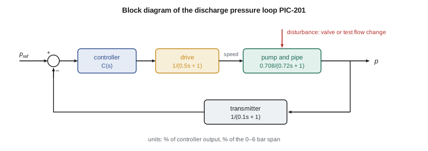
For a proportional controller, \(C(s) = K_c\), the forward path is \(G = K_c \times 0.708/((0.5s + 1)(0.72s + 1))\) and the feedback path is \(H = 1/(0.1s + 1)\). Applying the feedback rule and clearing fractions gives the closed-loop transfer function from setpoint to true pressure:
For \(K_c = 4\), the program multiplies out the polynomials to get a denominator of \(0.036s^3 + 0.482s^2 + 1.32s + 3.832\). Its roots, the closed-loop poles, are at −10.9 and \(-1.23 \pm 2.87j\): the feedback has pulled the two slow real poles together and off the real axis into a complex pair, so the closed loop will oscillate slightly as it settles. The DC gain is \(2.832/3.832 = 0.739\): with proportional control alone, the pressure settles 26 percent short of a setpoint change. Lesson 9 explains why and how to remove the error.
A feature of the closed-loop transfer function deserves attention. The transmitter's lag appears as a zero in the numerator, \(0.1s + 1\), because the transfer function is to the true pressure, not to the measured one. Had Owen asked for the transfer function to the measured pressure, the zero would vanish. The choice of output matters, and a design report should say which is meant.
# Block diagram algebra for the discharge pressure loop, and a state-space model of the drive train
import math, cmath
def pmul(a, b):                       # polynomial product, coefficients highest power first
    r = [0.0]*(len(a) + len(b) - 1)
    for i, x in enumerate(a):
        for j, y in enumerate(b): r[i + j] += x*y
    return r
def padd(a, b):
    n = max(len(a), len(b)); a = [0.0]*(n - len(a)) + a; b = [0.0]*(n - len(b)) + b
    return [x + y for x, y in zip(a, b)]
def roots(p):                         # Durand-Kerner iteration for all roots of a polynomial
    p = [c/p[0] for c in p]; n = len(p) - 1
    z = [complex(0.4, 0.9)**k for k in range(n)]
    for _ in range(500):
        z = [zi - sum(c*zi**(n - k) for k, c in enumerate(p)) / math.prod(zi - zj for j, zj in enumerate(z) if j != i)
             for i, zi in enumerate(z)]
    return sorted(z, key=lambda w: (round(w.real, 6), w.imag))
fmt = lambda p: " + ".join(f"{c:.4g} s^{len(p)-1-i}" if len(p)-1-i > 1 else (f"{c:.4g} s" if len(p)-1-i == 1 else f"{c:.4g}") for i, c in enumerate(p))

# Forward path: controller Kc, drive lag 1/(0.5s+1), pump-and-pipe 0.708/(0.72s+1); feedback: transmitter 1/(0.1s+1)
Kc = 4.0
num_G = [0.708 * Kc]; den_G = pmul([0.5, 1.0], [0.72, 1.0]); num_H = [1.0]; den_H = [0.1, 1.0]
# Closed loop T = G/(1 + G H) = num_G den_H / (den_G den_H + num_G num_H)
num_T = pmul(num_G, den_H); den_T = padd(pmul(den_G, den_H), pmul(num_G, num_H))
print("Closed loop P(s)/Pref(s) =")
print("   numerator:  ", fmt(num_T)); print("   denominator:", fmt(den_T))
print(f"   DC gain {num_T[-1]/den_T[-1]:.3f}: a steady error of {100*(1 - num_T[-1]/den_T[-1]):.0f} % of a setpoint step")
print("   closed-loop poles:", ", ".join(f"{z.real:.2f}{z.imag:+.2f}j" for z in roots(den_T)))

# State-space model of motor, flexible coupling and pump: x = [motor speed, pump speed, coupling twist]
Jm, Jp, kt, bp = 0.090, 0.060, 6.0e3, 0.648
A = [
    [0.0, 0.0, -kt/Jm],
    [0.0, -bp/Jp, kt/Jp],
    [1.0, -1.0, 0.0],
]
B = [1/Jm, 0.0, 0.0]               # input: motor torque
C = [0.0, 0.0, kt]                 # output: torque measured by the coupling transducer
# Characteristic polynomial det(sI - A) by the Faddeev-LeVerrier algorithm
def charpoly(A):
    n = len(A); I = [ [float(i == j) for j in range(n)] for i in range(n)]
    M = [row[:] for row in I]; c = [1.0]
    for k in range(1, n + 1):
        AM = [ [sum(A[i][l]*M[l][j] for l in range(n)) for j in range(n)] for i in range(n)]
        ck = -sum(AM[i][i] for i in range(n)) / k; c.append(ck)
        M = [ [AM[i][j] + ck*I[i][j] for j in range(n)] for i in range(n)]
    return c
cp = charpoly(A)
print("\nDrive train det(sI - A) =", fmt(cp))
for z in roots(cp):
    if abs(z.imag) > 1e-6: print(f"   pole {z.real:.2f} {z.imag:+.1f}j rad/s -> torsional mode at {abs(z)/2/math.pi:.1f} Hz, zeta {-z.real/abs(z):.5f}")
    else: print(f"   pole {z.real:.2f} rad/s -> rigid-body speed mode, time constant {(-1/z.real if z.real else float('inf')):.2f} s")

# Simulate a 10 N m motor torque step (RK4) and record the peak transducer torque
def f(x, u): return [sum(A[i][j]*x[j] for j in range(3)) + B[i]*u for i in range(3)]
x, dt, Tpk = [0.0, 0.0, 0.0], 2e-5, 0.0
for n in range(int(0.2/dt)):
    k1 = f(x, 10.0); k2 = f([a + dt/2*b for a, b in zip(x, k1)], 10.0)
    k3 = f([a + dt/2*b for a, b in zip(x, k2)], 10.0); k4 = f([a + dt*b for a, b in zip(x, k3)], 10.0)
    x = [a + dt/6*(p + 2*q + 2*r + s) for a, p, q, r, s in zip(x, k1, k2, k3, k4)]
    Tpk = max(Tpk, kt*x[2])
print(f"Peak coupling torque after a 10 N m motor step: {Tpk:.2f} N m (rigid-body share {10*Jp/(Jm+Jp):.1f} N m)")Closed loop P(s)/Pref(s) = numerator: 0.2832 s + 2.832 denominator: 0.036 s^3 + 0.482 s^2 + 1.32 s + 3.832 DC gain 0.739: a steady error of 26 % of a setpoint step closed-loop poles: -10.92+0.00j, -1.23-2.87j, -1.23+2.87j Drive train det(sI - A) = 1 s^3 + 10.8 s^2 + 1.667e+05 s + 7.2e+05 pole -4.32 rad/s -> rigid-body speed mode, time constant 0.23 s pole -3.24 -408.2j rad/s -> torsional mode at 65.0 Hz, zeta 0.00794 pole -3.24 +408.2j rad/s -> torsional mode at 65.0 Hz, zeta 0.00794 Peak coupling torque after a 10 N m motor step: 9.53 N m (rigid-body share 4.0 N m)
State variables
The state of a system is the smallest set of variables that, together with the inputs from time zero on, determines its future completely. For a lumped physical system the state variables are naturally the quantities that describe its energy stores: the level in each tank, the temperature of each thermal mass, the velocity of each mass and the deflection of each spring. The number of state variables equals the order of the system. Writing one first-order equation for each and collecting them in matrix form gives the state-space model:
Here x is the state vector, u the input vector, y the output vector, and A, B, C and D are matrices of constant coefficients for a linear time-invariant system. A describes how the states influence each other, B how the inputs drive them, C which combinations are measured and D any direct path from input to output, which is zero for most physical plants.
A state model of the drive train
The two-inertia drive train of Lesson 2 has three energy stores: the kinetic energy of each rotor and the strain energy of the coupling. Choosing the state as motor speed \(\omega_m\), pump speed \(\omega_p\) and coupling twist \(\theta = \theta_m - \theta_p\), with motor torque as the input and the torque measured by the transducer as the output, the equations of Lesson 2 become
The eigenvalues of A are the poles of the system. They are the roots of the characteristic polynomial \(\det(sI - A)\), which the program computes by the Faddeev-LeVerrier algorithm, a simple recursion that needs only matrix products and traces. The result is \(s^3 + 10.8s^2 + 166{,}700s + 720{,}000\), with one real pole at −4.32 rad/s and a complex pair at \(-3.24 \pm 408j\) rad/s. The real pole is the rigid-body speed mode: with no motor slip characteristic in the model (the drive supplies torque directly), the only damping is the pump load, and the train settles with a time constant of 0.23 s. The complex pair is the 65 Hz torsional mode of Lesson 2, with a damping ratio of only 0.008, because the model contains no damping in the coupling itself.
The simulation shows what happens when the motor torque steps by 10 N·m. The coupling torque rings at 65 Hz and peaks at 9.5 N·m within 0.2 s, more than twice the 4.0 N·m share it would carry if the train were rigid at the instant of the step. The ringing is real: torque transducers on test stands often show it during fast speed changes, and it is one reason Gilles leaves the drive's ramp at 5 s.
From state space to transfer function
Taking Laplace transforms of the state equations with zero initial conditions gives \(sX = AX + BU\), so \(X = (sI - A)^{-1}BU\), and the transfer function matrix is
Its denominator is \(\det(sI - A)\), which confirms that the eigenvalues of A are the poles. The reverse conversion is not unique: any transfer function has infinitely many state-space realizations, because the state variables can be chosen in many ways. Standard forms such as the controllable canonical form, in which the coefficients of the denominator appear in the last row of A, are convenient for simulation. Owen's simulations of the pressure loop use the physically meaningful form instead, one state per lag, so that each state can be compared with a measurement during commissioning.
Worked problem
State model of the pressure plant
Write a state-space model of the pressure process 0.708/((0.5s + 1)(0.72s + 1)(0.1s + 1)) using the drive speed, the true pressure and the measured pressure as states, all in percent.
Show solution
- Drive: \(0.5\dot x_1 + x_1 = u\), so \(\dot x_1 = -2x_1 + 2u\).
- Pump and pipe: \(0.72\dot x_2 + x_2 = 0.708x_1\), so \(\dot x_2 = 0.983x_1 - 1.389x_2\).
- Transmitter: \(0.1\dot x_3 + x_3 = x_2\), so \(\dot x_3 = 10x_2 - 10x_3\).
- \(A = \begin{bmatrix}-2 & 0 & 0\\ 0.983 & -1.389 & 0\\ 0 & 10 & -10\end{bmatrix}\), \(B = [2\;\;0\;\;0]^T\), \(C = [0\;\;0\;\;1]\).
Answer: A is lower triangular, so its eigenvalues are the diagonal entries −2, −1.389 and −10, the poles of the transfer function, as expected for lags in series.
Why both views matter
Block diagrams make the structure of a control system visible, and they are the natural language for discussing where a disturbance enters, where a sensor sits and what a controller acts on. Transfer functions make single-loop design quick. State-space models are better whenever a system has several inputs and outputs, as TL-3 does once level, pressure, flow and temperature are all controlled together; when initial conditions matter; or when nonlinear effects such as saturation are simulated. Modern controller design methods, such as state feedback and observers, are built entirely in state space, and MEC-450 and the mechatronics course build on them. For the single-loop designs of this course, Owen uses transfer functions for design and state-space simulation to check.
Common mistakes
MistakeChaining blocks for elements that load each other.
InsteadModel interacting elements together; block diagrams assume one-way signal flow.
MistakeUsing the wrong sign at a summing junction.
InsteadNegative feedback subtracts the measurement; check the sign before reducing.
MistakeAssuming the closed-loop zero from a feedback lag appears in every output.
InsteadIt appears in the transfer function to the true output, not to the measured one.
MistakeChoosing state variables that are not independent.
InsteadUse one variable per independent energy store; the count equals the order.
MistakeExpecting a unique state-space model for a transfer function.
InsteadRealizations are not unique; choose physical states when you need to compare with measurements.
Summary and key terms
- Series blocks multiply, parallel blocks add, and a negative feedback loop reduces to G/(1 + GH).
- The loop transfer function L = GH and the characteristic equation 1 + L = 0 govern stability and performance.
- With Kc = 4, the pressure loop's closed-loop poles are −10.9 and −1.23 ± 2.87j, and the DC gain is 0.739.
- State-space models ẋ = Ax + Bu, y = Cx + Du use one state per energy store; eigenvalues of A are the poles.
- The drive train model has a rigid-body pole at −4.32 rad/s and a lightly damped 65 Hz torsional pair.
- G(s) = C(sI − A)⁻¹B + D converts state space to a transfer function; the reverse conversion is not unique.
- Block diagram
- A diagram of blocks, holding transfer functions, connected by signals.
- Summing junction
- A point where signals are added or subtracted.
- Loop transfer function
- The product of all transfer functions around a feedback loop.
- Closed-loop transfer function
- The transfer function from a loop's reference input to its output.
- State
- The smallest set of variables that, with future inputs, determines a system's future.
- State vector
- The column of state variables in a state-space model.
- System matrix
- The matrix A that describes how the states influence each other.
- Eigenvalue
- A root of det(sI − A); a pole of the system.
- Realization
- A state-space model that has a given transfer function.
- Controllable canonical form
- A standard realization with the denominator coefficients in one row of A.
Practice problems
Work each problem on paper first, then reveal the answer to check.
Reduce G = 10/(s + 1) with unity negative feedback.
Show answer
10/(s + 11).
Two blocks 2/(s + 1) and 3/(s + 2) are in parallel. What is the combined transfer function?
Show answer
(5s + 7)/((s + 1)(s + 2)).
How many state variables does a model with two tanks and a pipe inertance need?
Show answer
Three.
In the program, raise Kc to 8. What is the DC gain of the closed loop?
Show answer
5.664/6.664 = 0.85, a 15 percent error.
What are the eigenvalues of a triangular A matrix?
Show answer
Its diagonal entries.
Why does the coupling torque overshoot after a motor torque step?
Show answer
The lightly damped torsional mode rings, doubling the instantaneous transmitted torque before it decays.
Lesson quiz · 5 questions
Score 60% or more to complete this lesson.
Create a free account to save your progress, take quizzes and earn a certificate.