
JAVA-270 · Lesson 11 of 12 · 25 min
UML for communication
▶ Video coming soon A video version of this lesson is on the way.
Tuesday, March 28, 2028, the last regular session of the term. In three weeks Hamza will stand in front of Ingrid, Leif, Odile and Kofi and explain how the new CounterApp is put together. Odile does not read Java, Kofi reads a little, and Leif reads a lot but will not have time to read 3,000 lines. Ingrid hands out a sheet of paper and a pencil to everyone in the room and asks Hamza to draw the sell-a-part use case from last month. Tonight's lesson is about the pictures software people draw to explain designs to each other, and in particular about the Unified Modeling Language.
What UML is, and how to use it
The Unified Modeling Language, UML, was created in the mid-1990s when Grady Booch, James Rumbaugh and Ivar Jacobson merged their three competing notations at Rational Software. The Object Management Group adopted it as a standard in 1997, and the current version, UML 2.5.1, was published in 2017. It defines fourteen kinds of diagram. Most working developers use three or four of them, and use those loosely.
Martin Fowler's short book UML Distilled describes three ways people use UML. As a sketch, it is a quick, partial drawing on a whiteboard or paper to talk about one idea, and is thrown away afterward. As a blueprint, it is a complete, detailed design handed to someone else to build from. As a programming language, the diagrams are the program, and code is generated from them. Fowler, and most teams today, find the sketch by far the most valuable. That is the use this lesson teaches: draw just enough to make one point clearly, in a notation the other people in the room can read.
| Diagram | Shows | Good for at Second Gear |
|---|---|---|
| Class diagram | Types, their members and how they relate | Explaining the domain model and the ports |
| Sequence diagram | Objects exchanging messages over time | Walking through one use case, such as selling a part |
| State machine diagram | States of one object and the events that move it | Repair states, so Odile can check the rules |
| Package or component diagram | Groups of code and the dependencies between them | Showing the hexagon and the dependency rule |
| Activity diagram | Steps and decisions in a process | The end-of-day cash-up procedure |
Class diagrams
A class diagram shows types and the relationships between them. Each class is a box with up to three compartments: the name, the attributes and the operations. A leading plus sign means public, a minus sign private, a hash sign protected and a tilde package-private. Attribute types follow a colon, as in minus onHand colon int. An interface is marked with the stereotype interface in guillemets above its name, and a record can be marked the same way with the stereotype record. On a sketch, show only the members that matter to the point you are making.
The relationships matter more than the boxes. A solid line is an association: one class holds or knows about another. Numbers at each end, called multiplicity, say how many: 1, 0..1, * for many, or 1..* for at least one. A solid line with a hollow triangle pointing at the parent is generalization, which is Java's extends. A dashed line with a hollow triangle is realization, Java's implements. A dashed arrow is a dependency: one class uses another, for example as a parameter, without holding it. A filled diamond is composition, a whole that owns its parts so that the parts do not outlive it, which is how an aggregate root holds its lines.
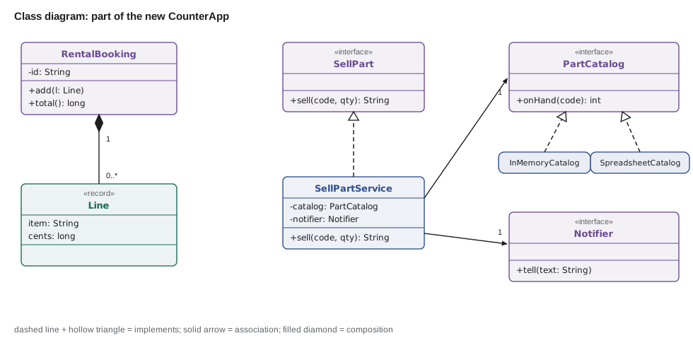
A class diagram and the code should agree. Here is the Java for most of the diagram above. Reading the two side by side is a good way to learn the notation: each implements is a dashed triangle, each field of an interface type is an association, and the private list inside RentalBooking is the composition.
import java.util.*;

public class Main {
    record Line(String item, long cents) {}
    static final class RentalBooking {                        // RentalBooking <>-- 0..* Line
        private final String id;
        private final List<Line> lines = new ArrayList<>();
        RentalBooking(String id) { this.id = id; }
        void add(Line l) { lines.add(l); }
        long total() { return lines.stream().mapToLong(Line::cents).sum(); }
    }

    interface SellPart { String sell(String code, int qty); }   // <<interface>>
    interface PartCatalog { int onHand(String code); }
    interface Notifier { void tell(String text); }

    static final class SellPartService implements SellPart {  // realization: dashed line, hollow triangle
        private final PartCatalog catalog;                    // association, multiplicity 1
        private final Notifier notifier;                      // association, multiplicity 1
        SellPartService(PartCatalog c, Notifier n) { catalog = c; notifier = n; }
        public String sell(String code, int qty) {
            int left = catalog.onHand(code) - qty;
            if (left < 2) notifier.tell(code + " low");
            return code + " sold, " + left + " left";
        }
    }

    public static void main(String[] args) {
        RentalBooking b = new RentalBooking("B-311");
        b.add(new Line("city bike", 2500));
        b.add(new Line("helmet", 500));
        System.out.println("booking total " + b.total());
        SellPart s = new SellPartService(code -> 3, text -> System.out.println("notify: " + text));
        System.out.println(s.sell("BELL", 2));
    }
}booking total 3000 notify: BELL low BELL sold, 1 left
What this code does
Each comment ties a line of code to a piece of the class diagram: the private list is the composition with Line, the implements clause is the realization and each interface-typed field is an association with multiplicity 1. The main method wires the service with two lambdas standing in for adapters. Selling 2 of 3 bells leaves 1, so the notifier is told the part is low before the result is printed.
Because a class diagram is just a description of types, it is easy to generate from a small model of them. Tools such as PlantUML go the other way: you write the diagram as text, and the tool draws it. Text diagrams fit well in a code repository, because they can be reviewed in a pull request and kept next to the code they describe. The next example prints PlantUML text for the ports of the hexagon from a list of records.
import java.util.*;

public class Main {
    enum Kind { INTERFACE, CLASS }
    record Type(String name, Kind kind, List<String> members) {}
    record Link(String from, String arrow, String to, String label) {}

    static String plantUml(List<Type> types, List<Link> links) {
        StringBuilder sb = new StringBuilder("@startuml\n");
        for (Type t : types) {
            sb.append(t.kind() == Kind.INTERFACE ? "interface " : "class ").append(t.name()).append(" {\n");
            t.members().forEach(m -> sb.append("  ").append(m).append("\n"));
            sb.append("}\n");
        }
        for (Link l : links) {
            sb.append(l.from()).append(" ").append(l.arrow()).append(" ").append(l.to());
            if (!l.label().isEmpty()) sb.append(" : ").append(l.label());
            sb.append("\n");
        }
        return sb.append("@enduml").toString();
    }

    public static void main(String[] args) {
        List<Type> types = List.of(
            new Type("SellPart", Kind.INTERFACE, List.of("+sell(code: String, qty: int): String")),
            new Type("PartCatalog", Kind.INTERFACE, List.of("+find(code: String): Optional<Part>", "+save(p: Part)")),
            new Type("SellPartService", Kind.CLASS, List.of("-catalog: PartCatalog")),
            new Type("SpreadsheetCatalog", Kind.CLASS, List.of("-path: Path")));
        List<Link> links = List.of(
            new Link("SellPartService", "..|>", "SellPart", ""),
            new Link("SellPartService", "-->", "PartCatalog", "1"),
            new Link("SpreadsheetCatalog", "..|>", "PartCatalog", ""));
        System.out.println(plantUml(types, links));
    }
}@startuml
interface SellPart {
+sell(code: String, qty: int): String
}
interface PartCatalog {
+find(code: String): Optional<Part>
+save(p: Part)
}
class SellPartService {
-catalog: PartCatalog
}
class SpreadsheetCatalog {
-path: Path
}
SellPartService ..|> SellPart
SellPartService --> PartCatalog : 1
SpreadsheetCatalog ..|> PartCatalog
@endumlWhat this code does
The program describes four types and three relationships as records and prints them in PlantUML's text format. The arrow ..|> is PlantUML's realization, a dashed line with a hollow triangle, and --> is an association. Pasting the output into PlantUML draws a class diagram of the sell use case's ports.
Sequence diagrams
A class diagram shows structure; a sequence diagram shows one interaction over time. Each participant is a box at the top with a dashed lifeline hanging down. Messages are horizontal arrows from one lifeline to another, in time order from top to bottom: a solid line with a filled arrowhead for a call, and a dashed line for a return. A thin rectangle on a lifeline, the activation bar, shows when that participant is busy. Frames labeled alt, opt or loop show conditions and repetition.
Sequence diagrams are the best tool for explaining a hexagonal design to people who do not read code, because they show the order in which things happen and which side of a port each step is on. Odile could follow the sell use case on Ingrid's sheet of paper even though she had never seen the classes.
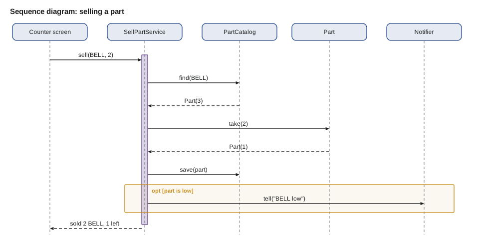
A sequence diagram can even be produced from a running program. The next example records each call as it happens and prints the trace in PlantUML's sequence syntax. Tracing a real run is a reliable way to draw an accurate diagram of legacy code whose behavior nobody remembers, which ties directly back to last week's lesson.
import java.util.*;

public class Main {
    static final List<String> trace = new ArrayList<>();
    static void call(String from, String to, String msg) { trace.add(from + " -> " + to + " : " + msg); }
    static void reply(String from, String to, String msg) { trace.add(from + " --> " + to + " : " + msg); }

    record Part(String code, int onHand) {
        Part take(int n) { call("Service", "Part", "take(" + n + ")"); Part p = new Part(code, onHand - n); reply("Part", "Service", "Part(" + p.onHand + ")"); return p; }
    }
    static final Map<String, Part> store = new TreeMap<>(Map.of("BELL", new Part("BELL", 3)));
    static Part find(String code) { call("Service", "Catalog", "find(" + code + ")"); Part p = store.get(code); reply("Catalog", "Service", "Part(" + p.onHand() + ")"); return p; }
    static void save(Part p) { call("Service", "Catalog", "save(" + p.code() + ")"); store.put(p.code(), p); }
    static void tell(String text) { call("Service", "Notifier", "tell(\"" + text + "\")"); }

    static String sell(String code, int qty) {
        call("Screen", "Service", "sell(" + code + ", " + qty + ")");
        Part after = find(code).take(qty);
        save(after);
        if (after.onHand() < 2) tell(code + " low");
        String result = "sold " + qty + " " + code + ", " + after.onHand() + " left";
        reply("Service", "Screen", result);
        return result;
    }

    public static void main(String[] args) {
        sell("BELL", 2);
        System.out.println("@startuml");
        trace.forEach(System.out::println);
        System.out.println("@enduml");
    }
}@startuml
Screen -> Service : sell(BELL, 2)
Service -> Catalog : find(BELL)
Catalog --> Service : Part(3)
Service -> Part : take(2)
Part --> Service : Part(1)
Service -> Catalog : save(BELL)
Service -> Notifier : tell("BELL low")
Service --> Screen : sold 2 BELL, 1 left
@endumlWhat this code does
Each step of the sell use case adds a line to the trace as it runs: a solid arrow for a call and a dashed arrow for a reply, in PlantUML's sequence syntax. The output lists the messages in the order they happened, from the screen's request through the catalog and the part to the low-stock notice and the final reply. Fed to PlantUML, it draws the same sequence diagram as the figure.
State machine diagrams
A state machine diagram shows the states one object can be in and the transitions between them. States are rounded rectangles; a filled circle marks the start and a circle with a ring the end. Each transition is an arrow labeled with the event that causes it, optionally followed by a guard in square brackets. This is the diagram that would have caught the done-means-two-things confusion from lesson 9 before any code was written, because Odile can read it and say that arrow is wrong.
The state machine for a repair, written as a transition table in code, can be checked and drawn at the same time. The next program stores the allowed transitions, rejects a move that is not on the diagram, and prints the PlantUML for the diagram from the same table, so the picture can never drift from the rules.
import java.util.*;

public class Main {
    enum State { BOOKED, IN_PROGRESS, WAITING_FOR_PARTS, FINISHED, COLLECTED }
    record Transition(State from, String event, State to) {}

    static final List<Transition> RULES = List.of(
        new Transition(State.BOOKED, "start", State.IN_PROGRESS),
        new Transition(State.IN_PROGRESS, "partMissing", State.WAITING_FOR_PARTS),
        new Transition(State.WAITING_FOR_PARTS, "partArrived", State.IN_PROGRESS),
        new Transition(State.IN_PROGRESS, "signOff", State.FINISHED),
        new Transition(State.FINISHED, "pay", State.COLLECTED));

    static State fire(State s, String event) {
        return RULES.stream().filter(t -> t.from() == s && t.event().equals(event)).map(Transition::to)
                    .findFirst().orElseThrow(() -> new IllegalStateException(event + " not allowed in " + s));
    }

    public static void main(String[] args) {
        State s = State.BOOKED;
        for (String e : List.of("start", "partMissing", "partArrived", "signOff", "pay")) {
            s = fire(s, e);
            System.out.println(e + " -> " + s);
        }
        try { fire(State.BOOKED, "pay"); } catch (IllegalStateException ex) { System.out.println("refused: " + ex.getMessage()); }

        System.out.println("@startuml");
        System.out.println("[*] --> BOOKED");
        RULES.forEach(t -> System.out.println(t.from() + " --> " + t.to() + " : " + t.event()));
        System.out.println("COLLECTED --> [*]");
        System.out.println("@enduml");
    }
}start -> IN_PROGRESS partMissing -> WAITING_FOR_PARTS partArrived -> IN_PROGRESS signOff -> FINISHED pay -> COLLECTED refused: pay not allowed in BOOKED @startuml [*] --> BOOKED BOOKED --> IN_PROGRESS : start IN_PROGRESS --> WAITING_FOR_PARTS : partMissing WAITING_FOR_PARTS --> IN_PROGRESS : partArrived IN_PROGRESS --> FINISHED : signOff FINISHED --> COLLECTED : pay COLLECTED --> [*] @enduml
What this code does
The RULES list is the state machine: each record is one arrow on the diagram, with the event that labels it. The fire method moves a repair through its life, including a trip to waiting for parts and back, and refuses paying for a repair that is only booked. The same list then prints PlantUML for a state diagram, so the drawing and the code always show the same rules.
Package diagrams and the bigger picture
For architecture, a package diagram shows packages as tabbed folders with dashed dependency arrows between them. It is the natural way to draw the layer rules of lesson 7 or the inward-pointing dependencies of lesson 8, and an arrow pointing the wrong way stands out at a glance. Simon Brown's C4 model builds on the same idea with four zoom levels: system context, containers, components and code. It is popular because it tells you which diagram to draw for which audience: a context diagram for Odile, a component diagram for Leif.
Whatever the notation, a few habits make diagrams communicate. Give each diagram a title that says what question it answers. Show only what that question needs, so leave out getters, constructors and unrelated classes. Use the ubiquitous language for names. Keep the number of boxes small enough to read, about seven to nine. Put a key on anything that is not standard UML. And date it, because a diagram that does not match the code is worse than no diagram.
| Symbol | Meaning | Java |
|---|---|---|
| Solid line, hollow triangle | Generalization | extends |
| Dashed line, hollow triangle | Realization | implements |
| Solid line or arrow | Association | A field referring to another type |
| Filled diamond | Composition | A private collection of parts owned by the whole |
| Hollow diamond | Aggregation | A shared reference; rarely worth drawing |
| Dashed arrow | Dependency | A parameter, local variable or static call |
| + - # ~ | Visibility | public, private, protected, package-private |
Try it yourself
Code from a class diagram
A sketch on the whiteboard shows an interface Notifier with operation +tell(text: String), a class TextNotifier that realizes Notifier, and a class Reminders with an association of multiplicity 1 to Notifier and an operation +remind(name: String). Write the code so that remind calls tell with Your bike is ready, NAME and TextNotifier prints text: followed by the message.
The program should print text: Your bike is ready, Ana.
public class Main {
    public static void main(String[] args) {
        System.out.println("diagram not coded yet");
    }
}
Try it yourself
Add a transition
Odile looks at the repair state diagram and says customers sometimes withdraw a repair before work starts. Add a state WITHDRAWN and a transition from BOOKED on the event withdraw, so that firing withdraw on a booked repair works.
The program should print withdraw -> WITHDRAWN and then the line BOOKED --> WITHDRAWN : withdraw as the last transition.
import java.util.*;

public class Main {
    enum State { BOOKED, IN_PROGRESS }
    record Transition(State from, String event, State to) {}

    static final List<Transition> RULES = List.of(
        new Transition(State.BOOKED, "start", State.IN_PROGRESS));

    static State fire(State s, String event) {
        return RULES.stream().filter(t -> t.from() == s && t.event().equals(event)).map(Transition::to)
                    .findFirst().orElseThrow(() -> new IllegalStateException(event + " not allowed in " + s));
    }

    public static void main(String[] args) {
        try { System.out.println("withdraw -> " + fire(State.BOOKED, "withdraw")); }
        catch (IllegalStateException e) { System.out.println("refused: " + e.getMessage()); }
        RULES.forEach(t -> System.out.println(t.from() + " --> " + t.to() + " : " + t.event()));
    }
}
Common mistakes
MistakeDrawing every class and every getter.
InsteadShow only what the diagram's one question needs.
MistakeConfusing extends and implements arrows.
InsteadGeneralization is a solid line with a hollow triangle; realization is dashed.
MistakeTreating a diagram as finished documentation.
InsteadUse sketches to communicate and keep any lasting diagram as text beside the code.
MistakeLetting diagrams drift from the code.
InsteadGenerate them from the code or a shared table, or date them and redraw.
MistakeUsing developer jargon on diagrams for the business.
InsteadName things in the ubiquitous language.
Summary and key terms
- The Unified Modeling Language, standardized in 1997 and now at version 2.5.1, defines fourteen diagram types, of which a few are widely used.
- UML can serve as a sketch, a blueprint or a programming language; the sketch is the most valuable.
- Class diagrams show types, members with visibility symbols and relationships: association with multiplicity, generalization for extends, realization for implements, dependency and composition.
- Sequence diagrams show participants' lifelines and the messages between them in time order, and suit explaining a use case.
- State machine diagrams show states and the events that move between them, and are easy for the business to check.
- Package diagrams and Simon Brown's C4 model show architecture at different levels.
- Text tools such as PlantUML keep diagrams in the repository and can be generated from code.
- Good diagrams answer one question, use the ubiquitous language and stay small.
- UML
- The Unified Modeling Language, a standard notation for software diagrams.
- Sketch
- A quick, partial diagram drawn to discuss one idea.
- Class diagram
- A diagram of types, their members and their relationships.
- Association
- A relationship in which one class holds or knows about another.
- Multiplicity
- The number of objects at one end of an association, such as 1 or 0..*.
- Generalization
- The UML relationship that corresponds to extends.
- Realization
- The UML relationship that corresponds to implements.
- Composition
- A whole that owns its parts, drawn with a filled diamond.
- Sequence diagram
- A diagram of messages between participants over time.
- Lifeline
- The dashed vertical line below a participant in a sequence diagram.
- State machine diagram
- A diagram of one object's states and the events that change them.
- PlantUML
- A tool that draws UML diagrams from a text description.
Practice problems
Work each problem on paper first, then reveal the answer to check.
Which arrow shows that SpreadsheetCatalog implements PartCatalog?
Show answer
A dashed line with a hollow triangle pointing at PartCatalog.
What does 0..* at the Line end of an association mean?
Show answer
A booking can have any number of lines, including none.
Which diagram would you draw to walk Odile through selling a part?
Show answer
A sequence diagram.
Why keep diagrams as PlantUML text in the repository?
Show answer
They can be reviewed in pull requests and stay next to the code.
What is a filled diamond?
Show answer
Composition: the whole owns its parts.
Lesson quiz · 5 questions
Score 60% or more to complete this lesson.
Create a free account to save your progress, take quizzes and earn a certificate.