
ELE-480 · Lesson 7 of 12 · 21 min
Distance protection of transmission lines
The 138 kV line from Lincoln Road to Hollis is 40 km (25 miles) long. Overcurrent relays are a poor fit for it: the current for a fault at the far end depends heavily on how many generators and lines are in service, so a relay set for the strongest system would be blind under the weakest, and one set for the weakest would overreach into the next line under the strongest. Distance relays avoid that problem by measuring the impedance between the relay and the fault, computed from the voltage and current at the relay location. Because line impedance is proportional to length, the measured impedance tells the relay how far away the fault is, almost independently of the source strength. Distance protection, device 21, is the workhorse of transmission line protection across the United States.
Measuring impedance
For a three-phase or phase-to-phase fault, a distance element divides the phase-to-phase voltage by the difference of the corresponding phase currents: for a BC fault, Z = (V_B − V_C)/(I_B − I_C). That ratio equals the positive-sequence impedance from the relay to the fault, whatever the fault current. Six measuring loops cover all faults: three phase-to-phase loops and three phase-to-ground loops. Numerical relays evaluate all six continuously.
Ground faults need a correction, because the fault loop includes the return path through ground, whose impedance per kilometer differs from the positive-sequence impedance. A phase-to-ground element uses the phase voltage and the phase current plus a compensated residual current:
With the right zero-sequence compensation factor k₀, the ground element measures the same positive-sequence impedance to the fault as the phase elements, so one set of reach settings serves both. The Hollis line has Z₁ = 3.2 + j16.0 Ω and Z₀ = 12 + j48 Ω, which give k₀ = 0.678 at −4.1°.
Stepped zones
A distance relay cannot set its reach to exactly 100 % of the line. Measurement errors in CTs, VTs and the relay, uncertainty in the line impedance data, CVT transients and the effects of fault resistance all add up to perhaps 10 to 20 %. A relay set at 100 % could overreach into the next line and trip for a fault beyond the remote bus. Distance protection therefore uses stepped zones.
| Zone | Typical reach | Time delay | Purpose |
|---|---|---|---|
| Zone 1 | 80 to 90 % of the line | None | Fast clearing of most of the line without overreaching the remote bus |
| Zone 2 | 120 % or more of the line, but short of the next line's Zone 1 | About 0.3 s | Covers the rest of the line; backs up the remote bus |
| Zone 3 | Line plus 120 % of the longest next line, if load allows | About 1 s or more | Remote backup for adjacent lines |
| Reverse zone | Behind the relay | Used in pilot schemes | Detects faults behind the relay for blocking logic |
import cmath, math
ZL  = complex(3.2, 16.0)      # Lincoln Road - Hollis, 40 km, positive sequence, primary ohms
Z0L = complex(12.0, 48.0)     # zero sequence
ZN  = complex(4.8, 24.0)      # Hollis - Grafton, 60 km (the next line)
k = (800/5)/(138000/115)      # CT ratio / VT ratio converts primary to secondary ohms
pol = lambda z: f"{abs(z):6.2f} ohm at {math.degrees(cmath.phase(z)):5.1f} deg"
print("line impedance:       ", pol(ZL), f"  secondary {abs(ZL)*k:.2f} ohm")
zones = {'Zone 1 (85 % of line, no delay)': 0.85*abs(ZL),
         'Zone 2 (120 % of line, 0.3 s)': 1.20*abs(ZL),
         'Zone 3 (line + 120 % of next, 1.0 s)': abs(ZL) + 1.20*abs(ZN)}
for n, r in zones.items(): print(f"{n:38s} {r:6.2f} ohm primary, {r*k:5.2f} ohm secondary")
print("Zone 2 limit, line + 50 % of next line:", f"{abs(ZL) + 0.5*abs(ZN):.2f} ohm")
k0 = (Z0L - ZL)/(3*ZL)
print("zero-sequence compensation k0 =", f"{abs(k0):.3f} at {math.degrees(cmath.phase(k0)):.1f} deg")
# Infeed at Hollis: for a fault 50 % along the next line, Hollis adds current from its own source
for ratio in (0.0, 1.0, 2.0):
    zapp = ZL + (1 + ratio)*0.5*ZN
    print(f"infeed ratio {ratio:.1f}: apparent impedance {abs(zapp):6.2f} ohm  (true {abs(ZL + 0.5*ZN):.2f})")
def in_mho(z, reach, ang=math.degrees(cmath.phase(ZL))):
    zr = cmath.rect(reach, math.radians(ang)); return abs(z - zr/2) < abs(zr)/2
# Loadability check in the style of NERC PRC-023: 150 % of a 900 A rating at 0.85 pu voltage and 30 degrees
I = 1.5*900; V = 0.85*138e3/math.sqrt(3)
zload = cmath.rect(V/I, math.radians(30))
print("\nloadability point:", pol(zload))
for n, r in list(zones.items()) + [('Zone 3 extended for infeed', 60.0)]:
    print(f"  {n.split(' (')[0]:28s} reach {r:5.1f} ohm: load point inside? {in_mho(zload, r)}")
r = 10
while not in_mho(zload, r): r += 0.5
print(f" a mho circle at the line angle first reaches the load point at about {r:.1f} ohm")line impedance: 16.32 ohm at 78.7 deg secondary 2.18 ohm Zone 1 (85 % of line, no delay) 13.87 ohm primary, 1.85 ohm secondary Zone 2 (120 % of line, 0.3 s) 19.58 ohm primary, 2.61 ohm secondary Zone 3 (line + 120 % of next, 1.0 s) 45.69 ohm primary, 6.09 ohm secondary Zone 2 limit, line + 50 % of next line: 28.55 ohm zero-sequence compensation k0 = 0.678 at -4.1 deg infeed ratio 0.0: apparent impedance 28.55 ohm (true 28.55) infeed ratio 1.0: apparent impedance 40.79 ohm (true 28.55) infeed ratio 2.0: apparent impedance 53.03 ohm (true 28.55) loadability point: 50.17 ohm at 30.0 deg Zone 1 reach 13.9 ohm: load point inside? False Zone 2 reach 19.6 ohm: load point inside? False Zone 3 reach 45.7 ohm: load point inside? False Zone 3 extended for infeed reach 60.0 ohm: load point inside? False a mho circle at the line angle first reaches the load point at about 76.0 ohm
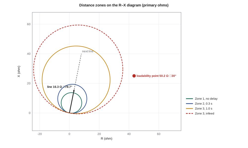
The program converts the zone reaches to secondary ohms, which is what the relay's settings use. With 800:5 CTs (ratio 160) and 138 kV:115 V VTs (ratio 1200), secondary impedance is primary impedance times 160/1200, or 0.133. The 16.32 Ω line is 2.18 Ω secondary. Zone 1 at 85 % is 13.87 Ω primary, 1.85 Ω secondary; Zone 2 at 120 % is 19.58 Ω, 2.61 Ω secondary, comfortably below the limit of the line plus half the next line, 28.55 Ω, so it will not reach far into the Hollis–Grafton line. Zone 3 at the line plus 120 % of the 60 km Hollis–Grafton line is 45.69 Ω, 6.09 Ω secondary.
Mho and quadrilateral characteristics
Each zone's shape on the R–X diagram is its characteristic. The mho characteristic is a circle through the origin whose diameter is the reach, drawn along the line angle. It is inherently directional, because it passes through the origin, and it naturally keeps its distance from the load region near the R axis. Its weakness is limited coverage of fault resistance, especially for short lines, where the circle is small. The quadrilateral characteristic is a polygon with independent reach settings in the reactive and resistive directions; it can cover much more fault resistance and is favored for ground elements and short lines, at the cost of more settings and greater care near the load region.
Numerical relays usually polarize their mho elements with positive-sequence memory voltage, which makes the circle expand toward the source during a fault and improves its coverage of fault resistance without changing its reach along the line. That dynamic expansion is one reason mho elements perform better in service than their static circles suggest.
Infeed and outfeed
Zone 3 at Lincoln Road is meant to back up the Hollis–Grafton line. But for a fault on that line, the Hollis station adds its own fault current, called infeed. The relay at Lincoln Road measures its own voltage and current, and its voltage includes the drop caused by the Hollis current flowing in the faulted part of the next line, so the impedance it measures is larger than the true impedance to the fault:
Here Z_x is the impedance from Hollis to the fault, I_H the infeed from Hollis and I_LR the current from Lincoln Road. The program shows the consequence for a fault halfway along the next line, whose true impedance is 28.55 Ω: with an infeed ratio of 1 the relay sees 40.79 Ω, and with a ratio of 2 it sees 53.03 Ω, outside the 45.69 Ω Zone 3. Infeed makes distance relays underreach. Nadine has Leo rerun the study with realistic infeed from the planning model and extend Zone 3 to about 60 Ω so that it still covers the end of the Hollis–Grafton line under normal infeed. Outfeed, where some current leaves the faulted path, has the opposite effect and can make a relay overreach; it occurs with tapped loads and some parallel-line configurations.
Load encroachment and loadability
Under heavy load, the impedance a distance relay sees is the voltage divided by the load current, which falls as load rises. If a long-reaching Zone 3 extends far enough toward the R axis, a heavy load during a stressed system condition can look like a fault. That happened during several major North American blackouts, when Zone 3 relays tripped heavily loaded but unfaulted lines and spread the cascade. NERC's relay loadability standard, PRC-023, now requires transmission line relays to stay quiet at 150 % of the line's highest seasonal rating, evaluated at 0.85 pu voltage and a 30° load angle, for lines at 200 kV and above and for lower-voltage lines selected by the planning coordinator.
Larchmont applies the same test to its 138 kV lines as good practice. The Hollis line is rated 900 A, so the test current is 1350 A at 0.85 pu voltage, an impedance of 50.2 Ω at 30°. The program checks every zone, including the extended 60 Ω Zone 3, and finds the load point outside them all: a mho circle at the line angle would not reach it until its reach exceeded about 76 Ω. Where a needed reach would encroach on load, relays offer load-encroachment logic, a region around the load angle in which the distance elements are blocked unless the measured impedance moves out of it, or quadrilateral elements with limited resistive reach.
Power swings and other complications
After a disturbance, generators in different parts of the system swing against each other, and the impedance seen by a distance relay moves slowly across the R–X plane. A stable swing can pass through a distance zone and cause an unwanted trip. Power-swing blocking measures how fast the impedance moves: a fault makes it jump almost instantly, a swing makes it travel at a finite rate, so a slow transit between two concentric characteristics identifies a swing and blocks the distance elements. Out-of-step tripping logic, applied at selected locations, deliberately separates the system at chosen points when a swing is unstable.
Other complications include series-compensated lines, where series capacitors upset the proportionality of impedance and distance, multi-terminal lines, where infeed from a tap changes every zone, and mutual coupling between parallel lines, which affects ground elements. Each has well-developed solutions in relay guides, and each is a reason that transmission protection settings are reviewed by a second engineer before they are applied.
Worked problem
Zone 2 timing and the remote bus
A fault occurs on the Hollis bus itself. Which zone at Lincoln Road sees it, how long does it take to trip, and why is that acceptable?
Show solution
- The Hollis bus is 16.32 Ω from Lincoln Road, beyond the 13.87 Ω Zone 1 but inside the 19.58 Ω Zone 2.
- Zone 2 trips after its 0.3 s delay plus the breaker time, about 0.37 s in total.
- The Hollis bus protection should clear the fault in under 0.1 s, so Zone 2 at Lincoln Road acts only as remote backup and has 0.3 s of margin to coordinate.
Answer: Zone 2 sees it and would trip after about 0.37 s, but only if the Hollis bus protection failed to clear it first.
Common mistakes
MistakeSetting Zone 1 to 100 % of the line.
InsteadMeasurement errors could make it overreach into the next line; 80 to 90 % is usual.
MistakeForgetting zero-sequence compensation for ground elements.
InsteadWithout k₀, ground elements measure the wrong impedance and misreach.
MistakeSetting Zone 3 from line impedances alone.
InsteadInfeed makes the relay underreach; check with realistic fault studies.
MistakeIgnoring load when extending reach.
InsteadLong reaches can trip heavily loaded lines; check loadability and use load encroachment logic.
Summary and key terms
- Distance relays measure impedance to the fault, which is nearly independent of source strength.
- Phase loops use phase-to-phase quantities; ground loops need zero-sequence compensation k₀.
- Zone 1 reaches 80 to 90 % instantaneously; Zone 2 covers the rest with about 0.3 s; Zone 3 is remote backup.
- Secondary ohms equal primary ohms times CT ratio divided by VT ratio.
- Mho characteristics are directional circles; quadrilaterals cover more fault resistance.
- Infeed causes underreach; outfeed can cause overreach.
- Loadability checks and load encroachment logic keep distance relays from tripping on heavy load.
- Distance relay (21)
- A relay that trips when the impedance it measures falls inside a set characteristic.
- Reach
- The impedance along the line angle to the edge of a zone.
- Zero-sequence compensation (k₀)
- A factor that corrects ground loop measurements for the ground return path.
- Mho characteristic
- A circular zone through the origin of the R–X plane.
- Infeed
- Fault current added by another source between the relay and the fault.
- Load encroachment
- Logic that blocks distance elements in the region of the R–X plane where heavy load lies.
- Power-swing blocking
- Logic that blocks distance elements when the impedance moves slowly as in a swing.
Practice problems
Work each problem on paper first, then reveal the answer to check.
A line is 20 Ω primary. With CT ratio 240 and VT ratio 1200, what is it in secondary ohms?
Show answer
20 × 240/1200 = 4 Ω.
Why is Zone 1 set short of the remote bus?
Show answer
To avoid overreaching into the next line because of measurement errors.
Line 10 Ω, infeed ratio 1.5, fault 4 Ω beyond the remote bus. What impedance does the relay see?
Show answer
10 + 2.5 × 4 = 20 Ω.
What load point does the loadability test use for a 900 A rating at 138 kV?
Show answer
1350 A at 0.85 pu voltage and 30°, about 50 Ω.
Why do quadrilateral elements suit short lines?
Show answer
Their resistive reach can be set independently to cover fault resistance.
How does power-swing blocking tell a swing from a fault?
Show answer
A swing moves the impedance slowly; a fault makes it jump.
Lesson quiz · 5 questions
Score 60% or more to complete this lesson.
Create a free account to save your progress, take quizzes and earn a certificate.