
ELE-480 · Lesson 6 of 12 · 21 min
Directional and ground fault protection
An overcurrent relay knows how much current flows but not which way. On a radial feeder that does not matter, because fault current can only flow outward from the source. At Lincoln Road's 138 kV bus it matters a great deal. The station sits between Hollis and Grafton, so a fault on the Hollis line draws current toward it from Lincoln Road and, through the bus, from Grafton as well. A nondirectional overcurrent relay on the Grafton line terminal would see that current and could trip the healthy Grafton line. Directional elements add the missing information: they compare the fault current with a reference quantity, the polarizing quantity, and decide whether the fault lies in front of the relay or behind it.
How a directional element decides
For a fault in front of the relay, on the protected line, the current measured by the relay lags the driving voltage by roughly the angle of the impedance between the relay and the fault, typically 60 to 85° for overhead lines. For a fault behind the relay, the current through the relay reverses, so its angle shifts by about 180°. A directional element measures the angle between the operating current and a polarizing quantity whose angle does not depend on the fault's direction, and declares forward if that angle falls within about 90° of a characteristic angle called the maximum torque angle (MTA).
Electromechanical directional relays produced a torque proportional to |V||I|cos(φ − MTA), where φ is the angle by which the current lags the polarizing voltage; positive torque closed the contact. Numerical relays compute the same quantity, or an equivalent impedance-based measure, from phasors. The name maximum torque angle survives from the electromechanical era: it is the angle at which the element is most sensitive.
Polarizing quantities
For phase faults, a common choice is quadrature polarization: the current in phase A is compared with the voltage between phases B and C, which is 90° out of phase with phase A's voltage and remains healthy during a phase-A fault. Using a healthy voltage avoids the problem that a close-in fault collapses the faulted phase's own voltage to almost zero, leaving nothing to compare against. Numerical relays also use memory voltage, the pre-fault voltage remembered for a few cycles, for close-in three-phase faults where all voltages collapse together.
For ground faults there are two main choices. Zero-sequence voltage polarization compares 3I₀ with −3V₀, the residual voltage, which appears only during ground faults. Zero-sequence current polarization uses the current in the neutral of a grounded-wye transformer at the station as the reference, which works where the residual voltage at a strong source is too small to measure reliably. Negative-sequence polarization compares 3I₂ with −3V₂ and is popular in numerical relays because it is unaffected by zero-sequence mutual coupling between parallel lines on the same towers, a phenomenon that can confuse zero-sequence elements.
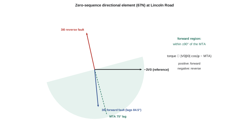
The Lincoln Road ground directional element
Leo models the zero-sequence network of the Hollis line terminal. Behind the relay is Lincoln Road's own zero-sequence source impedance; in front is the 40 km line, with a zero-sequence impedance of 12 + j48 Ω, and the Hollis source beyond it. For a ground fault on the line, zero-sequence current flows from the Lincoln Road bus into the line, and the residual voltage at the bus is the voltage drop across the source impedance behind the relay. For a ground fault behind the relay, on the bus or the Grafton line, zero-sequence current flows the other way, from Hollis through the line into the bus.
import cmath, math
deg = math.degrees
# 138 kV line Lincoln Road (relay) to Hollis, zero-sequence network in per unit on 100 MVA
z0_behind = complex(0.0050, 0.0520)*1.2      # Lincoln Road source and transformer neutrals behind the relay
z0_line   = complex(12.0, 48.0)/190.44       # 40 km line, ohms to per unit
z0_remote = complex(0.0080, 0.0700)          # Hollis end
def ground_fault(x):                          # fraction x of the line from the relay; returns I0 at relay, V0 at relay
    za = z0_behind + x*z0_line; zb = z0_remote + (1 - x)*z0_line
    i0_total = 1.0                            # scale: only angles and ratios matter here
    i0_relay = i0_total*zb/(za + zb)          # share flowing from the relay end toward the fault
    v0 = -i0_relay*z0_behind                  # zero-sequence voltage at the relay bus
    return i0_relay, v0
MTA = 75                                      # maximum torque angle of the 67N element, degrees
for name, (i0, v0) in (('forward, 50 % of line', ground_fault(0.5)),):
    lag = (deg(cmath.phase(-v0) - cmath.phase(i0)) + 180) % 360 - 180
    print(f"{name}: 3I0 lags -3V0 by {lag:6.1f} deg; torque cos(lag - MTA) = {math.cos(math.radians(lag - MTA)):+.2f} -> {'forward' if math.cos(math.radians(lag - MTA)) > 0 else 'reverse'}")
# Reverse fault at the Lincoln Road bus: zero-sequence current now comes from Hollis toward the bus,
# so the current measured into the line is negative while -V0 keeps the same angle
zsum = z0_behind + z0_line + z0_remote
i0r = -z0_behind/zsum                          # into-the-line current at the relay (per unit of fault I0)
v0r = -z0_behind*(z0_line + z0_remote)/zsum   # zero-sequence voltage at the bus
lag = (deg(cmath.phase(-v0r) - cmath.phase(i0r)) + 180) % 360 - 180
print(f"reverse fault at bus:   3I0 lags -3V0 by {lag:6.1f} deg; torque cos(lag - MTA) = {math.cos(math.radians(lag - MTA)):+.2f} -> {'forward' if math.cos(math.radians(lag - MTA)) > 0 else 'reverse'}")

# Sensitivity of the 25 kV feeder ground element (51N) to fault resistance at the feeder end
S, V = 100e6, 24.94e3; Ib = S/(math.sqrt(3)*V); Zb = V**2/S
z1 = complex(0.00520, 0.0520) + 0.36j + complex(0.11, 0.40)*12/Zb
z0 = 0.36j + complex(0.33, 1.35)*12/Zb
for rf in (0, 10, 20, 40, 80, 120):
    i = abs(3/(2*z1 + z0 + 3*rf/Zb))*Ib
print(f"Rf {rf:4d} ohm: 3I0 = {i:6.0f} A {'(below a 120 A pickup)' if i < 120 else ''}")forward, 50 % of line: 3I0 lags -3V0 by 84.5 deg; torque cos(lag - MTA) = +0.99 -> forward reverse fault at bus: 3I0 lags -3V0 by -102.4 deg; torque cos(lag - MTA) = -1.00 -> reverse Rf 0 ohm: 3I0 = 1277 A Rf 10 ohm: 3I0 = 874 A Rf 20 ohm: 3I0 = 580 A Rf 40 ohm: 3I0 = 330 A Rf 80 ohm: 3I0 = 174 A Rf 120 ohm: 3I0 = 117 A (below a 120 A pickup)
For a fault halfway along the line, 3I₀ lags −3V₀ by 84.5°, the angle of the zero-sequence source impedance behind the relay, and the torque with a 75° MTA is almost at its maximum: forward. For a fault at the Lincoln Road bus the current measured into the line reverses, the angle moves to −102°, and the torque is strongly negative: reverse. Note that the angle of a forward ground fault is set by the impedance behind the relay, not by the line; that is a useful fact to remember when choosing the MTA. Nadine sets it at 75°, close to the angle of the source impedances at this station, which leaves wide margins for both decisions.
Directional overcurrent applications
A directional element by itself only gives direction; it supervises an overcurrent element to make a directional overcurrent relay, device 67 for phase and 67N or 67G for ground. On Larchmont's 138 kV network, directional ground overcurrent relays back up the distance relays of lesson 7 and are especially valuable for high-resistance ground faults, which a distance relay may not see. They also form the fault detectors of the communication-aided schemes of lesson 8.
On distribution systems, directional elements appear wherever current can flow both ways: at the incoming breakers of a bus fed by two transformers, on closed-loop or network feeders, and increasingly on feeders with distributed generation. Lesson 12 shows that the solar plant on feeder F3 can push enough current backward through F3's breaker, during a fault on a neighboring feeder, to trip a nondirectional F3 relay. A directional element that blocks tripping for reverse faults solves that problem.
Ground fault protection on the 25 kV system
Distribution ground faults deserve special attention because they are the most common faults and the most variable. Larchmont's 25 kV feeders are four-wire, multigrounded: the neutral conductor runs with the phase conductors and is grounded at every pole with a transformer and at regular intervals between. Single-phase loads connect between a phase and the neutral, so some residual current flows all the time, and the ground relay's pickup must sit above it.
The program shows how fault resistance erodes the ground fault current at the end of a 12 km feeder: 1.28 kA bolted, 580 A through 20 Ω, 330 A through 40 Ω, 174 A through 80 Ω and 117 A through 120 Ω, just below a 120 A pickup. A ground element at 120 A therefore covers faults up to roughly 115 Ω at that location. Beyond that, the fault is a high-impedance fault, invisible to overcurrent protection, and the utility relies on the public reporting downed wires and on specialized detection algorithms.
Not every distribution system is multigrounded. Some industrial and older utility systems are ungrounded or grounded through high impedance, which limits ground fault current to a few amperes so that the system can keep running with one phase faulted. Ground faults on such systems are detected by the zero-sequence voltage they cause, measured with broken-delta VTs, and located by sensitive directional elements or by switching feeders out one at a time. The healthy phases rise toward full phase-to-phase voltage during the fault, so equipment insulation must be rated for it, and a second ground fault on another phase becomes a phase-to-phase fault.
Negative-sequence elements
Negative-sequence current appears during any unbalanced fault, phase-to-phase or ground, and is almost absent under balanced load. A negative-sequence overcurrent element (50Q, 51Q) can therefore be set well below load current, like a ground element, and it sees phase-to-phase faults that a phase element set above load would detect only slowly. On a feeder, a 51Q element can detect line-to-line faults at the far end that the phase element sees at barely twice pickup. Its pickup must be above the negative-sequence current from normal load unbalance, and it must coordinate with downstream phase and ground devices, which is easier if its curve is checked against them on the same time-current plot, scaled for the relationship between negative-sequence and phase currents in each fault type.
Worked problem
Choosing the MTA
On a different line terminal, the zero-sequence source impedance behind the relay has an angle of 70°, and the zero-sequence line impedance has an angle of 76°. Leo is tempted to set the MTA at the line angle. What angle will 3I₀ have relative to −3V₀ for a forward fault, and is an MTA of 76° acceptable?
Show solution
- For a forward fault, −3V₀ at the relay equals 3I₀ times the zero-sequence impedance behind the relay, so 3I₀ lags −3V₀ by the angle of that impedance, 70°.
- With an MTA of 76° the difference is 6°, and the torque is cos 6° ≈ 0.99 of maximum.
- A reverse fault would put 3I₀ about 180° away, giving a strongly negative torque.
Answer: 3I₀ lags −3V₀ by about 70°; an MTA of 76° works, though setting it near 70° matches the physics more closely.
Common mistakes
MistakeAssuming the forward-fault angle is the line angle for zero-sequence voltage polarization.
InsteadIt is the angle of the zero-sequence impedance behind the relay.
MistakePolarizing a phase element with its own faulted-phase voltage.
InsteadUse a healthy quadrature voltage or memory voltage, which survive close-in faults.
MistakeUsing zero-sequence elements on lines with strong mutual coupling without checking.
InsteadMutual coupling can mislead zero-sequence elements; negative-sequence polarization avoids it.
MistakeExpecting ground overcurrent relays to detect every downed conductor.
InsteadHigh-impedance faults can draw less current than the normal residual on the feeder.
Summary and key terms
- Directional elements compare the operating current with a polarizing quantity to decide forward or reverse.
- The decision uses an angle window of about ±90° around the maximum torque angle.
- Phase elements use quadrature or memory voltage; ground elements use −3V₀, neutral current or negative sequence.
- For zero-sequence voltage polarization, a forward fault's angle is set by the impedance behind the relay.
- Directional overcurrent (67, 67N) relays protect networks, parallel lines and feeders with generation.
- Fault resistance limits the reach of ground overcurrent elements; high-impedance faults may be undetectable.
- Negative-sequence elements see unbalanced faults with settings below load current.
- Polarizing quantity
- The reference signal against which a directional element measures the angle of the current.
- Maximum torque angle (MTA)
- The angle at which a directional element is most sensitive; the center of its forward region.
- Quadrature polarization
- Using the voltage between the two other phases as the reference for a phase element.
- Memory voltage
- Pre-fault voltage stored by a numerical relay for use when the voltage collapses.
- Residual voltage (3V₀)
- The sum of the three phase-to-ground voltages.
- Mutual coupling
- Zero-sequence magnetic coupling between parallel lines that share a right-of-way.
- Multigrounded system
- A four-wire distribution system whose neutral is grounded at many points.
Practice problems
Work each problem on paper first, then reveal the answer to check.
A forward ground fault puts 3I₀ 82° behind −3V₀. With an MTA of 75°, what is the relative torque?
Show answer
cos 7° ≈ 0.99, forward.
Why are negative-sequence directional elements immune to zero-sequence mutual coupling?
Show answer
Mutual coupling between lines is a zero-sequence effect.
Through what fault resistance can a 120 A ground element still see a fault at 12 km?
Show answer
Roughly 115 Ω, from the program's table.
What happens to the healthy phases during a ground fault on an ungrounded system?
Show answer
Their voltage to ground rises toward phase-to-phase voltage.
Why is a directional element needed on a feeder with a large solar plant?
Show answer
The plant can feed current backward through the feeder breaker for faults elsewhere.
Why does a 51Q element help on long feeders?
Show answer
It can be set below load current and sees far-end phase-to-phase faults.
Lesson quiz · 5 questions
Score 60% or more to complete this lesson.
Create a free account to save your progress, take quizzes and earn a certificate.