
ELE-480 · Lesson 12 of 12 · 23 min
Distributed resources, arc flash and the substation protection study
The last weeks of Leo's term bring the Lincoln Road review together. Three issues remain open on Nadine's list: the 9.9 MW solar plant on feeder F3, which was connected two years ago under older settings; the arc flash labels on the 25 kV switchgear, which must be recalculated now that the feeder settings have changed; and the cybersecurity of the new numerical relays, which can now be reached over the utility's network. After those, Leo assembles the study report that Nadine will review, seal and send for implementation. This lesson follows each issue and then the study as a whole.
Distributed energy resources and protection
Inverter-based resources such as solar plants, batteries and most modern wind turbines behave very differently from synchronous generators during faults. A synchronous machine can supply five to ten times its rated current into a nearby fault; an inverter's semiconductors cannot carry much more than their rating, so the inverter's controls limit its fault current to roughly 1.1 to 1.5 times rated current, and the shape, phase and sequence content of that current are decided by the control software rather than by physics. The program estimates the solar plant's contribution at about 1.2 times rated current, 275 A at 25 kV.
import math
S, V = 100e6, 24.94e3; Ib = S/(math.sqrt(3)*V); Zb = V**2/S
zs = complex(0.00520, 0.0520) + 0.36j          # source and transformer, per unit (lesson 2)
zkm = complex(0.11, 0.40)/Zb                    # feeder impedance per km
# 9.9 MW solar plant on feeder F3 at 8 km; its inverters contribute about 1.2 x rated current to faults
Ipv = 1.2*9.9e6/(math.sqrt(3)*V)/Ib             # per unit
zA, zB = zs + 8*zkm, 7*zkm                      # substation to plant, plant to a fault at 15 km
If_grid = 1/(zA + zB)                           # grid contribution with no plant
# Superposition: part of the plant's current returns toward the substation and opposes the relay current
i_relay = If_grid - Ipv*zB/(zA + zB)
print(f"inverter fault contribution about {Ipv*Ib:.0f} A")
print(f"F3 relay current for a fault at 15 km: {abs(If_grid)*Ib:5.0f} A without the plant, {abs(i_relay)*Ib:5.0f} A with it")
print(f"backfeed through F3 for a fault on F1: about {Ipv*Ib:.0f} A against an F3 pickup of 240 A")
# Arc flash at the 25 kV switchgear by the Lee method (used above the empirical range of IEEE 1584; conservative)
def lee(kv, ka, t, d_mm): return 2.142e6*kv*ka*t/d_mm**2       # cal/cm^2
I, D = 5.87, 2000                                                 # kA bolted fault, working distance mm
for label, t in (('instantaneous 50P + breaker', 0.083), ('maintenance mode (fast, low set)', 0.067),
                 ('time overcurrent only', 0.62 + 0.05)):
    e = lee(24.94, I, t, D); db = math.sqrt(2.142e6*24.94*I*t/1.2)
    print(f"{label:33s} {t*1000:4.0f} ms: {e:5.1f} cal/cm2 ({e*4.184:5.1f} J/cm2) at 2 m (6.6 ft); "
f"boundary {db/1000:4.1f} m ({db/304.8:4.1f} ft)")inverter fault contribution about 275 A F3 relay current for a fault at 15 km: 1650 A without the plant, 1628 A with it backfeed through F3 for a fault on F1: about 275 A against an F3 pickup of 240 A instantaneous 50P + breaker 83 ms: 6.5 cal/cm2 ( 27.2 J/cm2) at 2 m (6.6 ft); boundary 4.7 m (15.3 ft) maintenance mode (fast, low set) 67 ms: 5.3 cal/cm2 ( 22.0 J/cm2) at 2 m (6.6 ft); boundary 4.2 m (13.7 ft) time overcurrent only 670 ms: 52.5 cal/cm2 (219.8 J/cm2) at 2 m (6.6 ft); boundary 13.2 m (43.4 ft)
Three classic problems follow. The first is protection blinding: for a fault beyond the plant, part of the plant's current returns toward the substation and reduces the current the feeder relay sees. At Lincoln Road the effect is small, 1650 A without the plant and 1628 A with it, because the source is strong and the plant is modest; on a weak rural feeder with a large plant it can push faults near the end of the feeder below the relay's pickup. The second is sympathetic tripping: for a fault on feeder F1, the plant feeds about 275 A backward through F3's breaker toward the fault, above F3's 240 A pickup, so a nondirectional F3 relay could trip a healthy feeder. Nadine adds directional phase and ground elements (67P, 67N) to F3, set to trip only for forward faults. The third is the effect on reclosing: during the dead time of the F3 breaker or of a downstream recloser, the plant could keep the fault energized or form an island, so it must stop energizing the feeder before the reclose.
In the United States, the interconnection of distributed energy resources is governed by IEEE 1547-2018, Standard for Interconnection and Interoperability of Distributed Energy Resources with Associated Electric Power Systems Interfaces, which most states have adopted through their interconnection rules, together with each utility's technical requirements; inverters are certified to UL 1741, including its supplement for advanced grid-support functions. In Wisconsin, the state's distributed generation interconnection rules refer to IEEE 1547. IEEE 1547-2018 requires the plant to detect an unintentional island and stop energizing the feeder within two seconds, and also to ride through voltage and frequency disturbances within defined limits for its performance category rather than tripping at the first sign of trouble, because the sudden loss of many small generators during a system disturbance could make it worse.
Those two requirements pull in opposite directions, and the protection engineer's job is to reconcile them with the utility's reclosing. A two-second island detection limit is not compatible with a 0.5 s first reclose on F3, so Larchmont extends F3's first dead time to 3 s and adds a transfer trip from Lincoln Road to the plant whenever the F3 breaker opens, so that the plant disconnects in a fraction of a second instead of relying on its own island detection. The F3 reclosing relay also checks that the feeder is dead before closing.
Arc flash
An arcing fault releases intense heat, light, pressure and molten metal in a fraction of a second. A worker standing in front of energized switchgear when an arc flash occurs can suffer severe burns even without touching anything. The thermal hazard is measured as incident energy, the heat energy per unit area at the worker's position, in calories per square centimeter or joules per square centimeter (1 cal/cm² = 4.184 J/cm²). An incident energy of about 1.2 cal/cm² (5.0 J/cm²) is taken as the onset of a second-degree burn on bare skin, and the arc flash boundary is the distance at which the incident energy falls to that level.
In the United States, NFPA 70E, Standard for Electrical Safety in the Workplace, whose current edition is from 2024, requires employers to assess arc flash hazards, determine the incident energy or use prescribed PPE categories, label equipment and select arc-rated personal protective equipment. For electric utilities, OSHA's rules for electric power generation, transmission and distribution, 29 CFR 1910.269, also require employers to estimate the incident energy workers may be exposed to and to provide protective clothing accordingly.
The most widely used calculation method, IEEE 1584-2018, is an empirical model built from extensive arc tests. It covers three-phase systems from 208 V to 15 kV with bolted fault currents from 700 A to 106 kA, and several electrode configurations. Lincoln Road's 25 kV switchgear is above that range, so Leo uses the theoretical Lee method, which the standard and common practice accept above 15 kV and which is known to give conservative, often high, results. In the Lee method the incident energy is proportional to the voltage, the bolted fault current and the arcing time, and inversely proportional to the square of the working distance.
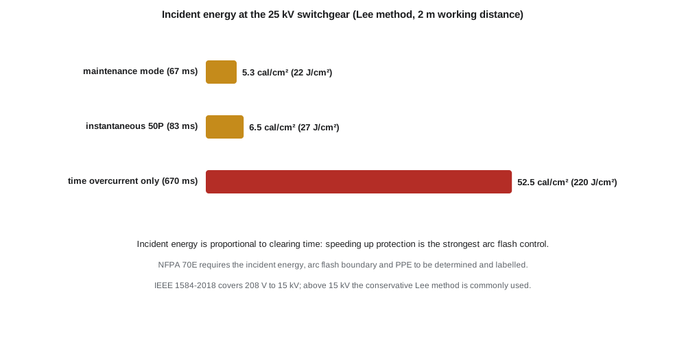
The program evaluates three clearing times for an arcing fault in the 25 kV switchgear, at a working distance of 2 m. If only the main breaker's time-overcurrent element clears the fault, in about 0.67 s, the incident energy is 52.5 cal/cm² and the arc flash boundary is about 13 m, a level at which no practical PPE makes energized work acceptable. With the instantaneous element of lesson 5, 83 ms, it is 6.5 cal/cm²; with a maintenance mode that switches in a sensitive, fast element while crews work on the switchgear, 67 ms, it is 5.3 cal/cm². Protection settings are the most powerful arc flash control a utility has, which is why the bus protection of lesson 11 and arc flash detection relays that respond to light and current are increasingly applied to medium-voltage switchgear. The best control of all remains de-energizing equipment before work, so that no incident energy exists.
Cybersecurity of protection systems
Numerical relays are computers, and many of them sit on networks. That brings great benefits, remote access to event records, settings management and IEC 61850 messaging, and new risks: a relay whose settings could be changed by an unauthorized person, or whose trip outputs could be operated remotely, is a hazard to the grid. NERC's Critical Infrastructure Protection (CIP) standards set mandatory requirements for the cyber systems that support the bulk electric system, and they apply to many protection systems at transmission substations. They require utilities to identify and categorize their cyber systems by impact, protect them within electronic security perimeters, control and log access, manage configuration changes and patches, monitor for and respond to security events, and train staff.
Larchmont's practices at Lincoln Road follow the same defensive principles. Relays sit on an isolated substation network behind a security gateway, and remote engineering access passes through an authenticated, logged and encrypted connection that is enabled only when needed. Every relay has unique strong passwords, unused communication ports and services are disabled, front-panel access is controlled, and settings are compared automatically with the approved versions so that any unauthorized change raises an alarm. Changes go through the same review and testing as any other settings change. These measures protect the protection system from both malicious and accidental changes, and they would have to be met even without a regulatory requirement, because a misconfigured relay is a safety and reliability hazard in itself.
The protection study
A protection study is the document that turns analysis into settings. It records the system data and assumptions, the fault study results, the protection philosophy, the settings for every function with the reasoning behind each, the coordination plots, the checks of CT performance and loadability, the arc flash results and the test requirements. It is reviewed by a second engineer, sealed by the responsible engineer, and kept so that the next engineer can understand why each setting was chosen.
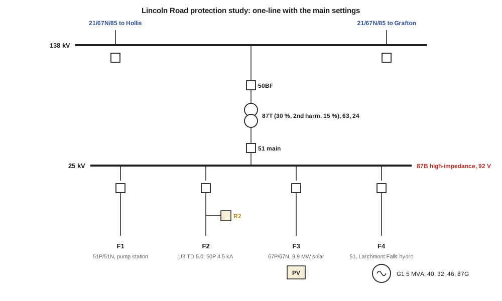
| Element | Main protection | Key settings (from this course) |
|---|---|---|
| 138 kV line to Hollis | Line differential, POTT, step distance, 67N | Zone 1 13.9 Ω, Zone 2 19.6 Ω at 0.3 s, Zone 3 60 Ω at 1.0 s; k₀ 0.678; MTA 75° |
| Transformer T1 | 87T, sudden pressure, 24, 51, 51N | Taps 2.615 A and 3.617 A; 0.3 pu pickup; 30 % slope; 15 % second harmonic; 87U 5 pu |
| 25 kV bus | High-impedance 87B, 50BF on all breakers | 92 V; BF timer 100 ms |
| Feeder F2 | 51P/50P, 51N, recloser R2, fuses | U3, 288 A, TD 5.0; 50P 4.47 kA; 51N 120 A; R2 200 A |
| Feeder F3 with solar | 67P/67N, transfer trip, extended reclose | Forward-only tripping; first dead time 3 s |
| Hydro G1 (feeder F4) | 87G, 40, 32, 46, 59N, 81, transfer trip | LOF offset 2.37 Ω, diameters 15.82 and 17.40 Ω; 32 at 1 % |
| Motor M1 (feeder F1) | 49 thermal, 50, 46, ground | Stall trip between 8 s start and 12 s safe time; 50 at 1744 A |
Before the settings go into service, Ravi's team tests every relay with secondary injection, checks every CT and VT circuit, verifies trip paths to every breaker, and performs end-to-end tests of the pilot schemes with synchronized test sets at both ends of each line. Once in service, the relays are maintained on intervals set by the utility's protection system maintenance program, which for transmission protection must meet NERC's maintenance standard. Every operation is analyzed from the relay's event records: a correct operation confirms the settings, and a misoperation is investigated until its cause is found and fixed.
Leo's report goes to Nadine with one open item that he flags himself: the minimum fault current at the end of feeder F2 is close enough to the ground element's sensitivity limit that a future extension of the feeder would need a review. Nadine adds a note to the study that any extension beyond 18 km triggers a new coordination check, signs the review sheet and tells him that noticing what the study does not cover is what makes a protection engineer.
Worked problem
Choosing a clearing time for maintenance mode
Larchmont wants the incident energy at the 25 kV switchgear, at 2 m working distance, kept below 8 cal/cm² while crews work near energized equipment. With the Lee method, V = 24.94 kV and I_bf = 5.87 kA, what is the longest clearing time allowed?
Show solution
- \[E = 2.142 \times 10^{6} \times 24.94 \times 5.87 \times \frac{t}{2000^2} = 78.4\,t\ \text{cal/cm}^2\]
- \[78.4\,t \le 8 \quad\Rightarrow\quad t \le 0.102\ \text{s}\]
- Both the 83 ms instantaneous element and the 67 ms maintenance mode meet the limit; the 0.67 s time-overcurrent clearing does not.
Answer: About 0.10 s, so the fast elements must be in service whenever crews work near the energized switchgear.
Common mistakes
MistakeAssuming inverter-based resources supply fault current like synchronous generators.
InsteadInverters limit fault current to about 1.1 to 1.5 times rating, and its character is set by their controls.
MistakeLeaving nondirectional relays on feeders with large distributed generation.
InsteadBackfeed during faults on other feeders can cause sympathetic trips; use directional elements.
MistakeTreating arc flash as a PPE problem only.
InsteadFast protection settings and de-energizing equipment reduce the hazard at its source.
MistakeApplying IEEE 1584-2018 equations outside their range.
InsteadAbove 15 kV, use an accepted method such as Lee and note its conservatism.
Summary and key terms
- Inverter-based resources supply limited, control-defined fault current.
- Distributed generation can blind feeder relays, cause sympathetic tripping and interfere with reclosing.
- IEEE 1547-2018 requires island detection within two seconds and ride-through of disturbances.
- Incident energy is proportional to clearing time; fast protection is the strongest arc flash control.
- NFPA 70E and OSHA 1910.269 require arc flash assessment and protection; IEEE 1584-2018 covers 208 V to 15 kV.
- Protection cybersecurity follows NERC CIP principles: perimeters, access control, change management and monitoring.
- A protection study documents data, reasoning, settings and tests, and is independently reviewed.
- Inverter-based resource
- A generating or storage resource connected through power electronic inverters.
- Protection blinding
- Reduction of the current seen by a feeder relay because a downstream source feeds the fault.
- Sympathetic tripping
- Tripping of a healthy feeder by backfeed during a fault on another feeder.
- Ride-through
- The requirement that a generator stay connected through defined voltage and frequency disturbances.
- Incident energy
- The thermal energy per unit area at a worker's position during an arc flash.
- Arc flash boundary
- The distance at which incident energy falls to about 1.2 cal/cm².
- NERC CIP
- Mandatory cybersecurity standards for systems that support the bulk electric system.
Practice problems
Work each problem on paper first, then reveal the answer to check.
An inverter plant is rated 5 MW at 25 kV. Estimate its fault contribution at 1.2 pu.
Show answer
About 1.2 × 115.5 A ≈ 139 A.
Why did Larchmont extend F3's first reclose dead time?
Show answer
So the solar plant has stopped energizing the feeder before the breaker recloses.
If the clearing time halves, what happens to the incident energy by the Lee method?
Show answer
It halves.
What incident energy marks the arc flash boundary?
Show answer
About 1.2 cal/cm², or 5.0 J/cm².
Name two cybersecurity measures for substation relays.
Show answer
Unique strong passwords and disabled unused ports; also logged, authenticated remote access.
What should a protection study contain besides the settings?
Show answer
System data, fault studies, reasoning, coordination plots, CT and loadability checks, arc flash results and test requirements.
Lesson quiz · 5 questions
Score 60% or more to complete this lesson.
Create a free account to save your progress, take quizzes and earn a certificate.