
ELE-480 · Lesson 10 of 12 · 21 min
Generator and motor protection
Two rotating machines on Lincoln Road's feeders ask for protection that no feeder relay can give. On feeder F4, the Larchmont Falls hydro station has two 5 MVA, 4.16 kV generators, G1 and G2, each connected through its own step-up transformer to the 25 kV feeder. On feeder F1, a water utility's pumping station runs a 1500 hp, 4.16 kV induction motor, M1. Both machines are expensive, both can be damaged by conditions that are not faults at all, and both can harm the system as well as themselves. Larchmont owns the generator protection settings at Larchmont Falls; the water utility owns M1's, but Larchmont reviews them because the motor's starting current and fault contribution affect the feeder. Leo works through both with Nadine.
What can go wrong with a generator
A synchronous generator can suffer internal faults in its stator winding, faults in its field circuit, and a long list of abnormal conditions: loss of excitation, motoring, unbalanced loading, overexcitation, abnormal frequency, loss of synchronism and inadvertent energization while stopped. Many of these conditions do not draw large currents and would go unnoticed by overcurrent relays until damage was done. Generator protection is therefore a package of specialized functions, most of them provided today by one multifunction numerical relay with a backup relay for the most important ones.
| Device | Function | Condition |
|---|---|---|
| 87G | Generator differential | Phase faults in the stator winding |
| 59N, 27TN | Neutral overvoltage, third-harmonic undervoltage | Stator ground faults (95 % plus the last 5 % near neutral) |
| 40 | Loss of field | Loss or severe reduction of excitation |
| 32 | Reverse power | Motoring when the prime mover fails |
| 46 | Negative-sequence overcurrent | Unbalanced loading or open phases |
| 24 | Volts per hertz | Overexcitation of the generator and its transformer |
| 81 | Over/underfrequency | Abnormal frequency; islanding |
| 51V | Voltage-restrained overcurrent | Backup for system faults |
| 78 | Out of step | Loss of synchronism |
| 50/27 | Inadvertent energization | Breaker closed onto a stopped machine |
Stator faults
Phase-to-phase faults in the stator are cleared by generator differential protection, which compares currents at the neutral and terminal ends of each phase winding; there is no transformer in the zone, so no ratio, phase shift or inrush complications, and the relay can be very sensitive and fast.
Ground faults need a different approach because of how generators are grounded. To limit the damage a stator ground fault does to the iron core, medium and large generators are grounded through a high impedance, usually a distribution transformer with a resistor on its secondary, which limits the ground fault current to a few amperes. The fault cannot be detected by current, but it shifts the neutral voltage. A neutral overvoltage element (59N) across the grounding resistor detects ground faults over about 95 % of the winding from the terminals; faults near the neutral produce too little voltage. The last few percent are covered by watching the third-harmonic voltage that every generator produces at its neutral and terminals, which changes distinctly when the neutral end is faulted, or by injecting a low-frequency signal into the neutral.
Loss of field
If a generator's excitation fails, it no longer produces its own magnetic field from the rotor. It continues to deliver real power, speeds up slightly and runs as an induction generator, drawing large reactive power from the system to magnetize itself. That can overheat the rotor and stator ends and depress system voltage. Viewed from the generator terminals, the apparent impedance moves from the load region in the first quadrant into the fourth quadrant, toward a point near the machine's reactances.
Loss-of-field relays (40) use offset mho circles in the negative-reactance region of the R–X plane. A common scheme uses two zones, both offset by half the transient reactance X′d/2 below the origin: zone 1 with a diameter of 1.0 pu, tripped after about 0.1 s, catches loss of field at heavy load; zone 2 with a diameter equal to the synchronous reactance Xd, delayed about 0.5 to 1 s to ride through stable power swings, catches loss of field at light load.
import math
# Larchmont Falls hydro unit G1: 5 MVA, 4.16 kV; CT 800/5, VT 4200/120
S, V = 5e6, 4.16e3
Zb = V**2/S; k = (800/5)/(4200/120)
Xd, Xdp = 1.10, 0.30
print(f"base impedance {Zb:.3f} ohm primary, {Zb*k:.2f} ohm secondary")
for name, off, dia in (('40 zone 1 (fast)', Xdp/2, 1.0), ('40 zone 2 (delayed)', Xdp/2, Xd)):
    print(f"{name:20s} offset {off*Zb*k:5.2f} ohm, diameter {dia*Zb*k:5.2f} ohm (secondary)")
# Reverse power: a hydro turbine motors at a small fraction of rating
print(f"\n32 reverse power at 1 % of rating: {0.01*S/1e3:.0f} kW primary, "
      f"{0.01*S/((800/5)*(4200/120)):.2f} W secondary (primary power / (CT ratio x VT ratio))")
# Negative-sequence capability I2^2 t = K (K = 40 assumed for this salient-pole unit)
K = 40
for i2 in (0.15, 0.30, 0.58):
    print(f"I2 = {i2:.2f} pu: permissible time {K/i2**2:7.0f} s")
# Pump-station motor M1: 1500 hp induction motor, 4.16 kV
P = 1500*746; eff, pf = 0.95, 0.90
FLA = P/(math.sqrt(3)*V*eff*pf); LRC = 6.0*FLA
print(f"\nmotor full-load current {FLA:.0f} A, locked-rotor current {LRC:.0f} A")
start, safe_hot = 8.0, 12.0
heat_start = (LRC/FLA)**2*start; heat_limit = (LRC/FLA)**2*safe_hot
print(f"start heating {heat_start:.0f} (x FLA^2 s) against a hot locked-rotor limit of {heat_limit:.0f}: margin {safe_hot - start:.0f} s")
print(f"50 instantaneous above asymmetrical starting current: about {1.6*LRC:.0f} A")
# Thermal model time to trip at 1.3 x FLA with a 30 minute heating time constant, starting cold
tau, SF = 1800, 1.15
for m in (1.2, 1.3, 1.5):
    t = tau*math.log(m**2/(m**2 - SF**2))
print(f"{m:.1f} x FLA: thermal trip after about {t/60:4.1f} min")base impedance 3.461 ohm primary, 15.82 ohm secondary 40 zone 1 (fast) offset 2.37 ohm, diameter 15.82 ohm (secondary) 40 zone 2 (delayed) offset 2.37 ohm, diameter 17.40 ohm (secondary) 32 reverse power at 1 % of rating: 50 kW primary, 8.93 W secondary (primary power / (CT ratio x VT ratio)) I2 = 0.15 pu: permissible time 1778 s I2 = 0.30 pu: permissible time 444 s I2 = 0.58 pu: permissible time 119 s motor full-load current 182 A, locked-rotor current 1090 A start heating 288 (x FLA^2 s) against a hot locked-rotor limit of 432: margin 4 s 50 instantaneous above asymmetrical starting current: about 1744 A 1.2 x FLA: thermal trip after about 75.2 min 1.3 x FLA: thermal trip after about 45.8 min 1.5 x FLA: thermal trip after about 26.6 min
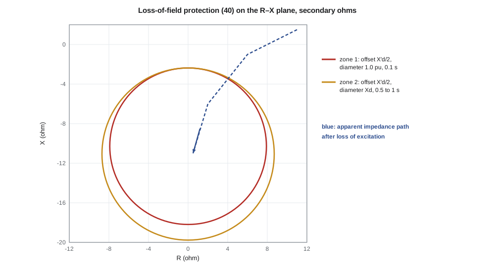
G1 has Xd = 1.10 pu and X′d = 0.30 pu on its own base. The base impedance at 4.16 kV and 5 MVA is 3.461 Ω primary; with 800:5 CTs and 4200:120 VTs, secondary ohms are primary ohms times 4.571, so the base is 15.82 Ω secondary. The program gives an offset of 2.37 Ω and diameters of 15.82 Ω for zone 1 and 17.40 Ω for zone 2. Nadine checks the circles against the generator's capability curve and its underexcitation limiter so that the relay does not trip a machine that is merely absorbing reactive power within its rated capability.
Motoring and unbalance
If a hydro unit's wicket gates close or its turbine loses water while the generator stays connected, the machine motors, drawing a small real power from the system to keep spinning. Motoring itself does not harm the generator, but it can damage the turbine: for steam turbines it overheats the last stages, and for hydro units it causes cavitation. The power drawn is small, often a few percent of rating or less for hydro units, so reverse power relays (32) must be sensitive. The program shows that 1 % of G1's rating, 50 kW primary, is only about 9 W at the relay's secondary terminals, which is why reverse power elements need accurate CTs and a time delay of several seconds to ride through power swings.
Unbalanced loads and open phases cause negative-sequence current, which induces double-frequency currents in the rotor surface and heats it. Generators are designed to tolerate a continuous negative-sequence current of a few to ten percent of rating and a short-time capability expressed as I₂²t = K, where K depends on the machine type. Using K = 40 for G1, the program shows a permissible time of about 1780 s at 0.15 pu, 444 s at 0.30 pu and 119 s at 0.58 pu, the negative-sequence current of an uncleared phase-to-phase fault at the terminals. A negative-sequence relay (46) follows that inverse-time characteristic.
Frequency and islanding
Underfrequency can damage turbine blades through resonance and overexcite the generator transformer, and overfrequency follows load rejection. Frequency relays (81) trip the unit after time delays that respect the turbine's limits. At the same time, generators must not trip too readily during system disturbances, when their support is most needed. NERC's generator frequency and voltage ride-through requirements, and the distributed-energy standards of lesson 12, set boundaries within which generators must stay connected. Protection engineers place the frequency settings outside those boundaries but inside the equipment limits.
Larchmont Falls must also be prevented from feeding an island. If the F4 feeder breaker opens, the hydro units could keep energizing part of the feeder at uncontrolled voltage and frequency, endangering crews and customers' equipment and making reclosing dangerous, because reclosing onto an unsynchronized island could damage the generators. The interconnection protection at Larchmont Falls trips the units on frequency, voltage and a transfer trip signal sent from Lincoln Road whenever the F4 breaker opens, and Lincoln Road's reclosing relay checks that the feeder is dead before reclosing.
Motor protection
Induction motors face a different set of threats: overload, locked rotor or stall, too many starts, unbalanced supply voltage, ground faults and phase faults. The most important protection is thermal. A motor drawing locked-rotor current heats its rotor many times faster than at full load, and the manufacturer specifies a safe stall time, hot and cold, during which the motor can carry locked-rotor current without damage. The starting time must be shorter than the safe stall time, with margin.
M1 draws about 182 A at full load and 6 times that, 1090 A, while starting. Its starting time is 8 s and its hot safe stall time 12 s, a margin of 4 s that the protection must preserve: the relay must allow the 8 s start but trip a stalled rotor before 12 s. Modern motor relays use a thermal model (49) that integrates the heating effect of the current, I² weighted by the time constant, and track the rotor's thermal state through starts and running, which is more accurate than fixed time-current curves.
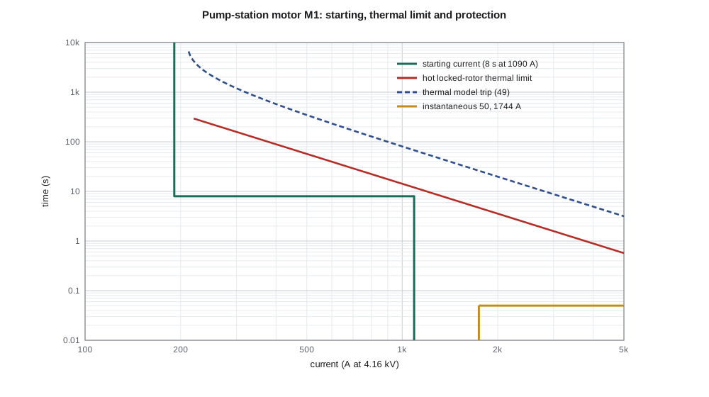
The program also sets M1's instantaneous element above the asymmetrical starting current, about 1.6 times the symmetrical locked-rotor current, giving 1744 A, so that the motor's first-cycle inrush does not trip it. With a 30-minute heating time constant and a 1.15 service factor, the thermal model would trip a sustained 1.3 times full-load overload after about 46 minutes from a cold start, and a 1.5 times overload after about 27 minutes. Other motor functions include negative-sequence or current-unbalance protection, because a few percent of voltage unbalance causes several times that much current unbalance and extra rotor heating, a limit on starts per hour, and ground fault protection with a core-balance CT around all three conductors.
Worked problem
Does the start fit inside the safe stall time?
The water utility proposes to replace M1's pump impeller with a larger one, which lengthens the start from 8 s to 11 s. With the hot safe stall time unchanged at 12 s, is the motor still protectable?
Show solution
- The relay must allow the start, so its stall trip time must exceed 11 s, with some margin, say 12 s.
- It must also trip a locked rotor before the 12 s hot safe stall time.
- There is no room for both: 11 s plus margin meets or exceeds 12 s.
- A speed switch that confirms the rotor is turning, or a reduced-voltage starter or drive that lowers the starting current, would be needed.
Answer: No; with an 11 s start and a 12 s hot stall limit there is no margin. A speed switch, soft starter or drive is needed.
Common mistakes
MistakeExpecting overcurrent relays to detect loss of field or motoring.
InsteadThese conditions draw modest currents; they need loss-of-field and reverse power functions.
MistakeAssuming a 59N element covers the whole stator winding.
InsteadIt covers about 95 %; third-harmonic or injection schemes cover the neutral end.
MistakeSetting reverse power elements without enough delay.
InsteadPower swings can briefly reverse the power; delays of several seconds prevent false trips.
MistakeSetting the motor stall trip without comparing start time and safe stall time.
InsteadThe trip must lie between the start time and the hot safe stall time.
Summary and key terms
- Generators need a package of functions for faults and abnormal conditions that draw little current.
- Generator differential clears stator phase faults; 59N and third-harmonic schemes cover ground faults on high-impedance grounded machines.
- Loss-of-field relays use offset mho circles in the negative-reactance region.
- Reverse power protects the prime mover from motoring; negative-sequence protection protects the rotor from unbalance.
- Frequency and islanding protection must respect both equipment limits and ride-through requirements.
- Motor protection centers on a thermal model that must permit starting and trip a stalled rotor.
- Starting time must be safely below the safe stall time.
- Loss of field (40)
- Protection that detects loss of a generator's excitation from its apparent impedance.
- Reverse power (32)
- Protection that trips a generator drawing real power from the system.
- Negative-sequence capability (I₂²t = K)
- The short-time limit on rotor heating from unbalanced current.
- High-impedance grounding
- Grounding a generator neutral through a resistor so ground fault current is a few amperes.
- Safe stall time
- The time a motor can carry locked-rotor current without damage.
- Thermal model (49)
- A relay function that tracks a motor's heating from the current and time.
- Islanding
- A generator continuing to energize part of the system after it is separated from the grid.
Practice problems
Work each problem on paper first, then reveal the answer to check.
G1's base is 15.82 Ω secondary and X′d = 0.30 pu. What is the loss-of-field offset?
Show answer
0.15 × 15.82 ≈ 2.37 Ω.
Why must reverse power elements on hydro units be sensitive?
Show answer
Motoring power is a small fraction of rating.
With K = 40, how long may a generator carry 0.2 pu negative-sequence current?
Show answer
40/0.04 = 1000 s.
Why is Larchmont Falls tripped by transfer trip when the F4 breaker opens?
Show answer
To prevent it from energizing an island and to allow safe reclosing.
A motor starts in 6 s and has a hot safe stall time of 10 s. Where should the stall trip be?
Show answer
Between about 7 and 9 s.
Why is the motor instantaneous element set at about 1.6 times locked-rotor current?
Show answer
To ride through the asymmetrical starting current.
Lesson quiz · 5 questions
Score 60% or more to complete this lesson.
Create a free account to save your progress, take quizzes and earn a certificate.